Shaping method of sealing gasket between windows and covering cap of cone-cylinder-shaped thermal shield

A molding method and technology of heat shield, applied in the direction of engine sealing, engine components, mechanical equipment, etc., can solve problems such as cracks, low reliability of sealing, loss of elasticity, etc.

Active Publication Date: 2015-09-02
湖北三江航天江北机械工程有限公司
View PDF6 Cites 11 Cited by
  • Summary
  • Abstract
  • Description
  • Claims
  • Application Information

AI Technical Summary

Problems solved by technology

Since the contact surface between the cover and the window of the heat shield is relatively complicated, the rubber gasket cannot fill the complex mating surface well when the cover and the window are pressed and fitted, and after aging, it cracks or loses elasticity, and the sealing effect is poor; Although the sealant can well fill the complex mating surface, it has a high requirement for the coating process. If the coating is uneven, the filling performance of the thinner part will decrease, and the reliability of the seal will not be high; and the heat shield of the throwing cover system In terms of flow, the forward / backward flow step difference between the outer cone of the cover and the outer cone of the heat shield should not affect its flight aerodynamic effect. Lower than the heat shield, the outer surface of the large end of the cover can be higher than the heat shield, that is, the airflow can pass through smoothly; the reverse airflow is the opposite, and generally no reverse airflow is allowed

Method used


Image

  • Shaping method of sealing gasket between windows and covering cap of cone-cylinder-shaped thermal shield
  • Shaping method of sealing gasket between windows and covering cap of cone-cylinder-shaped thermal shield
  • Shaping method of sealing gasket between windows and covering cap of cone-cylinder-shaped thermal shield

Examples


Embodiment Construction

[0029] Below in conjunction with accompanying drawing and specific embodiment the present invention will be described in further detail:

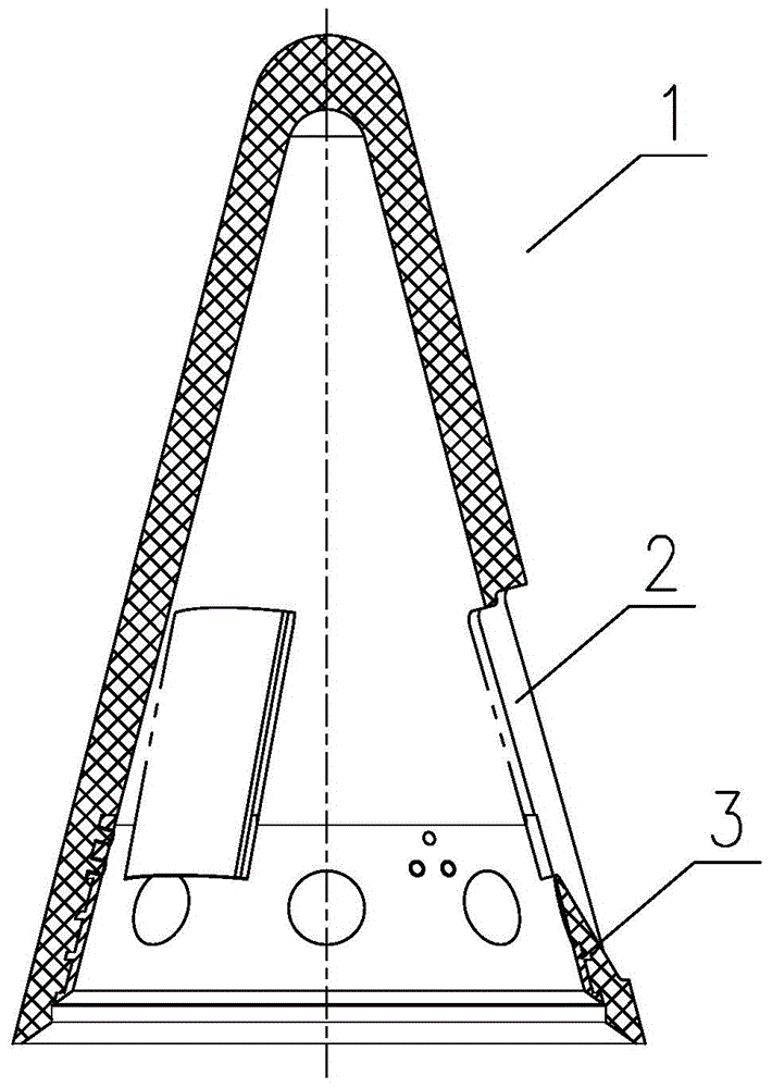
[0030] like figure 1 As shown, for a missile throwing system, the heat shield has a wall thickness of 20mm, a taper of 14.5°, a large end opening diameter of Φ302mm, and a height of about 470mm. The forming method steps of the gasket are as follows:

[0031] Step 1): The heat shield 1 is integrally molded by the glass fiber reinforced plastic body and the metal insert connecting ring 3, specifically: the heat shield 1 is formed by a four-column-guided high-precision mold at one time to ensure that the metal insert connecting ring at the large end of the heat shield 1 The relative position and coaxiality between 3 and the cover body, while ensuring the net size of the inner and outer cones of the heat shield 1, creates necessary conditions for the subsequent alignment and processing of the window 2. The heat shield 1 is made of high silicon...


PUM

PropertyMeasurementUnit
thicknessaaaaaaaaaa
heightaaaaaaaaaa

Abstract

The invention discloses a shaping method of a sealing gasket between windows and a covering cap of a cone-cylinder-shaped thermal shield. The shaping method of the sealing gasket between the windows and the covering cap of the cone-cylinder-shaped thermal shield includes following steps: using a numerical control machining method to process three windows on the thermal shield shaped through mould pressing, and using a near-net-shape forming method to shape the covering cap with a complex molding surface through mould pressing; performing repair so as to obtain matched intervals between the covering cap and the thermal shield windows so as to leave a space for manufacture of the sealing gasket; smearing the windows with prepared sealant, swearing the covering cap with a releasing agent, guaranteeing separation between the covering cap and the sealant, adhering the sealant to the thermal shield windows, and using a special shaping clamp matched with the thermal shield to tightly press the covering cap. The shaping method of the sealing gasket between the windows and the covering cap of the cone-cylinder-shaped thermal shield can guarantee seal performance of the thermal shield windows of a shield throwing system, and simultaneously can meet a downstream/upstream step increment between an external cone of the covering cap and an external cone of the thermal shield.

Description

technical field [0001] The invention relates to the technical field of sealing between a heat shield window and a cover of a missile throwing system, in particular to a sealing gasket forming method between a cone-shaped heat shield window and a cover. Background technique [0002] The throwing cover system is a protective device for the seeker part of the missile head, which is composed of heat shield, mouth cover, nozzle, adapter ring and other main parts. The heat shield and the cover are the key parts in the ejection system. When the flight Mach number is low, the ejection system opens the cover through the lateral force provided by the three asymmetric nozzles installed in the heat shield, and the optical The heat shield outside the hood is thrown away. Both the heat shield and the cover are molded with high-silicone phenolic resin and metal inserts. After the heat shield is molded, the three windows for installing the cover are processed by machining. The heat shield ...

Claims


Application Information

Patent Timeline
Patent Type & Authority Applications(China)
IPC IPC(8): B29C43/02F16J15/02
Inventor 杨江波初敬生晏述亮韩庆波付德生
Owner 湖北三江航天江北机械工程有限公司
Why Eureka
Try Eureka