
Device and method for detecting abrasion resistance of honeycomb-shaped ceramic-metal composite material

A technology of metal composite materials and honeycomb ceramics, which is applied in the direction of testing wear resistance, etc., can solve the influence of the comparison results of the wear resistance of wear samples, and cannot reflect the advantages of the wear resistance of honeycomb ceramic-metal composite materials. Quickly find out the wear resistance of honeycomb ceramic-metal composites and other issues, and achieve the effect of improving detection efficiency

Active Publication Date: 2015-09-02
KUNMING UNIV OF SCI & TECH
View PDF3 Cites 7 Cited by
  • Summary
  • Abstract
  • Description
  • Claims
  • Application Information

AI Technical Summary

Problems solved by technology

[0005] In view of the above-mentioned prior art, in order to solve the problem that only a single sample can be tested under one load during work, to avoid the impact of the abrasive particle size on the wear resistance performance of the wear sample, and to solve the problem that the existing device cannot quickly obtain different types and The advantages and disadvantages of the wear resistance of the honeycomb ceramic-metal composite materials with different volume fractions of ceramic particles solve the advantage that the traditional wear sample structure cannot reflect the wear resistance of the honeycomb ceramic-metal composite materials. The present invention provides a A detection device and detection method for the wear performance of a honeycomb ceramic-metal composite material

Method used


Image

  • Device and method for detecting abrasion resistance of honeycomb-shaped ceramic-metal composite material
  • Device and method for detecting abrasion resistance of honeycomb-shaped ceramic-metal composite material
  • Device and method for detecting abrasion resistance of honeycomb-shaped ceramic-metal composite material

Examples


Embodiment 1

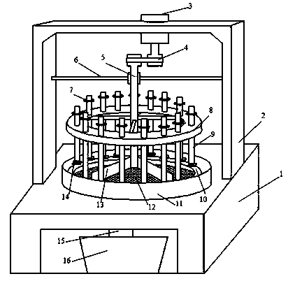
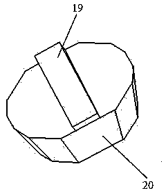
[0042] Embodiment 1: as Figure 1-9 As shown, a testing device for the wear performance of honeycomb ceramic-metal composite materials includes a workbench 1, a motor bracket 2, an adjustable speed motor 3, a conveyor belt 4, a rotating spindle 5, a rotating shaft bracket 6, a weight table 7, and a rotating shaft. Ring 8, sample rotating shaft 9, wear rail 10, retaining ring 11, abrasive screen 12, collecting plate 13, fixture 14, abrasive funnel 15, abrasive recovery cylinder 16, tough metal column 17, wear-resistant composite area 18, test Sample clamping step 19, feeding slope 20, electronic output instrument of hardness tester 21, electronic output instrument of quantitative metallographic microscope 22, electronic output instrument of precision balance 23, computer 24; wherein the workbench 1 and the motor bracket 2 are welded together, and the motor The bracket 2 and the adjustable speed motor 3 are connected together by bolts, the adjustable speed motor 3 drives the rot...

Embodiment 2

[0055] Embodiment 2: as Figure 1-9As shown, a testing device for the wear performance of honeycomb ceramic-metal composite materials includes a workbench 1, a motor bracket 2, an adjustable speed motor 3, a conveyor belt 4, a rotating spindle 5, a rotating shaft bracket 6, a weight table 7, and a rotating shaft. Ring 8, sample rotating shaft 9, wear rail 10, retaining ring 11, abrasive screen 12, collecting plate 13, fixture 14, abrasive funnel 15, abrasive recovery cylinder 16, tough metal column 17, wear-resistant composite area 18, test Sample clamping step 19, feeding slope 20, electronic output instrument of hardness tester 21, electronic output instrument of quantitative metallographic microscope 22, electronic output instrument of precision balance 23, computer 24; wherein the workbench 1 and the motor bracket 2 are welded together, and the motor The bracket 2 and the adjustable speed motor 3 are connected together by bolts, the adjustable speed motor 3 drives the rota...

Embodiment 3

[0058] Embodiment 3: as Figure 1-9 As shown, a testing device for the wear performance of honeycomb ceramic-metal composite materials includes a workbench 1, a motor bracket 2, an adjustable speed motor 3, a conveyor belt 4, a rotating spindle 5, a rotating shaft bracket 6, a weight table 7, and a rotating shaft. Ring 8, sample rotating shaft 9, wear rail 10, retaining ring 11, abrasive screen 12, collecting plate 13, fixture 14, abrasive funnel 15, abrasive recovery cylinder 16, tough metal column 17, wear-resistant composite area 18, test Sample clamping step 19, feeding slope 20, electronic output instrument of hardness tester 21, electronic output instrument of quantitative metallographic microscope 22, electronic output instrument of precision balance 23, computer 24; wherein the workbench 1 and the motor bracket 2 are welded together, and the motor The bracket 2 and the adjustable speed motor 3 are connected together by bolts, the adjustable speed motor 3 drives the rot...


PUM

PropertyMeasurementUnit
Densityaaaaaaaaaa
Densityaaaaaaaaaa
Densityaaaaaaaaaa

Abstract

The invention relates to a device and a method for detecting the abrasion resistance of a honeycomb-shaped ceramic-metal composite material, and belongs to the field of metal based composite materials. The device comprises a workbench, a motor support, a speed adjustable motor, a conveying belt, a rotation main shaft, a rotation shaft support, a weight table, a rotation ring, a specimen rotation shaft, an abrasion rail, a baffle ring, a ground material screen, a material collecting plate, a fixture, a ground material funnel, a ground material recycling cylinder, a toughness metal column, an abrasion-resistant compounding region, a specimen clamping step, a charge oblique surface, a sclerometer electronic output meter, a quantitative metallography microscopic electronic output meter, a precise scale electronic output meter and a computer. According to the device and method, a plurality of abraded specimens are detected under different loads and the same abrasion environment condition; superfine ground materials are filtered, so that the ground materials are kept in a reasonable range, further the accuracy of the detection result is facilitated; the unique abrasion resistance advantage of the structure of the honeycomb-shaped ceramic-metal composite material in the abrasion process is reflected reliably.

Description

technical field [0001] The invention relates to a detection device and a detection method for the wear performance of a honeycomb ceramic-metal composite material, belonging to the field of metal matrix composite materials. Background technique [0002] As a new type of wear-resistant composite material, honeycomb ceramic-metal composite material shows excellent performance in modern industrial production applications, and is gradually replacing traditional metal wear-resistant materials, such as high manganese steel, high chromium cast iron, etc. However, the comparison and evaluation of wear performance differences between different types of honeycomb ceramic-metal composites and between honeycomb ceramic-metal composites and traditional wear-resistant materials are few. At present, honeycomb ceramic-metal composites are mainly used in composite materials. Grinding rollers, grinding discs, liners and other products, and the service life of these products with large volume ...

Claims


Application Information

Patent Timeline
IPC IPC(8): G01N3/56
Inventor 蒋业华温放放刘光亮卢德宏李祖来山泉周谟金周荣
Owner KUNMING UNIV OF SCI & TECH
Learn More