Two-section evaporation separator

A technology of two-stage evaporation separation and separation zone, which is applied in the field of evaporation system, can solve the problems of occupying synthesis, decomposition, evaporation system capacity, high gas phase entrainment of urea, and affecting product quality, etc., to achieve better control of drainage indicators and improve absorption capacity , The effect of product quality improvement

Active Publication Date: 2015-09-09
ZHEJIANG ZHONGGONG PETROCHEMICAL EQUIP CO LTD
View PDF6 Cites 0 Cited by
  • Summary
  • Abstract
  • Description
  • Claims
  • Application Information

AI Technical Summary

Problems solved by technology

The current two-stage evaporative separator has the following problems: first, condensation products are easily generated above the internal mist separator, resulting in poor evaporation effect, resulting in high moisture content in the finished product, which affects product quality; second, the gas phase of the second-stage evaporative separator Entrained urea high
The amount of urea in the gas phase of the current separator is about 6% (weight ratio), and the 6% urea returns to the system for decomposition and synthesis, and then enters the evaporation system again, which wastes the decomposition steam and occupies the capacity of the synthesis, decomposition, and evaporation systems. Form a vicious circle and reduce production efficiency

Method used


Image

  • Two-section evaporation separator
  • Two-section evaporation separator
  • Two-section evaporation separator

Examples


Embodiment 1

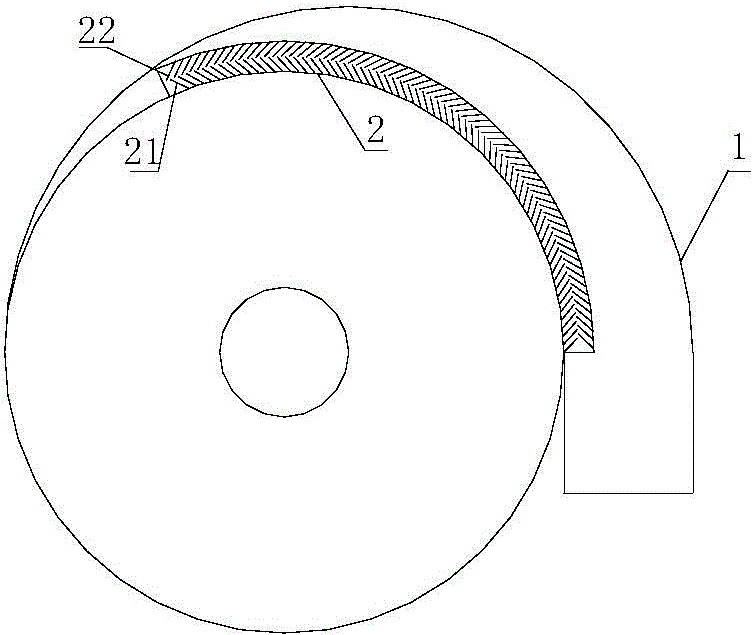
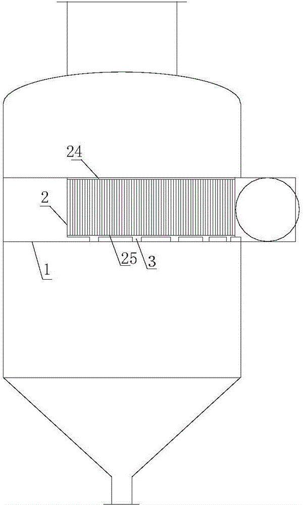
[0029] Second stage evaporative separator, such as Figure 1-3 As shown, including the volute 1, the inner wall of the volute 1 is provided with a mist separation area 2, the angle between the two ends of the mist separation area 2 and the center of the volute 1 is 40-180°, and the mist separation area 2 includes fins , the fins are made of titanium. The lower side of the fins is provided with a first fixed plate 24, and the upper side of the fins is provided with a second fixed plate 25. The fins include a first fin 21 and a second fin 22, between the first fin 21 and the second fin 22 The included angles between them are the same, and the number of the first fins 21 and the second fins 22 are both 45-100.

[0030] A liquid phase diversion area 3 is provided on the lower side of the volute 1, and the liquid phase diversion area 3 is connected with the mist separation area 2, and the number of three liquid phase diversion areas is six. The cross section of the liquid phase d...

Embodiment 2

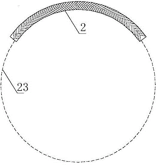
[0032] Second stage evaporative separator, such as Figure 1-3 As shown, including the volute 1, the inner wall of the volute 1 is provided with a mist separation area 2, the angle between the two ends of the mist separation area 2 and the center of the volute 1 is 40-180°, and the mist separation area 2 includes fins , the tangent line between the fin and the circle 23 where the mist separation zone is located is 45°. The lower side of the fins is provided with a first fixed plate 24, and the upper side of the fins is provided with a second fixed plate 25. The fins include a first fin 21 and a second fin 22, between the first fin 21 and the second fin 22 The included angles between them are the same, and the numbers of the first fins 21 and the second fins 22 are the same.

[0033] A liquid phase diversion area 3 is provided on the lower side of the volute 1, and the liquid phase diversion area 3 is connected with the mist separation area 2, and the number of three liquid ph...

Embodiment 3

[0035] Second stage evaporative separator, such as Figure 1-3 As shown, including the volute 1, the inner wall of the volute 1 is provided with a mist separation area 2, the angle between the two ends of the mist separation area 2 and the center of the volute 1 is 40-180°, and the mist separation area 2 includes fins , the tangent line between the fin and the circle 23 where the mist separation zone is located is 45°. The lower side of the fins is provided with a first fixed plate 24, and the upper side of the fins is provided with a second fixed plate 25. The fins include a first fin 21 and a second fin 22, between the first fin 21 and the second fin 22 The included angles between them are the same, and the number of the first fins 21 and the second fins 22 are both 66.

[0036] A liquid phase diversion area 3 is provided on the lower side of the volute 1, and the liquid phase diversion area 3 is connected with the mist separation area 2, and the number of three liquid phas...


PUM


Abstract

The invention relates to an evaporation system and discloses a two-section evaporation separator which comprises a volute (1), wherein an entrainment separation zone (2) is arranged at the inner side wall of the volute (1), each end of the entrainment separation zone (2) forms a 40-180-degree included angle with the circle center of the volute (1); the entrainment separation zone (2) comprises fins; a first fixed plate (24) is arranged at the lower sides of the fins; a second fixed plate (25) is arranged at the upper sides of the fins; the fins are divided into first fin (21) and second fin (22); the included angles between the first fin (21) and the corresponding second fins (22) are the same; six liquid phase guide zones (3) are formed at the lower side of the volute (1); the liquid phase guide zones (3) are connected with the entrainment separation zone (2). The two-section evaporation separator is mainly divided into the entrainment separation zone and the liquid phase guide zones; by virtue of the entrainment separation zone provided with the fins, the urea entrainment amount in a gas phase can be effectively lowered and the generation of side reaction is thoroughly avoided; the liquid phase guide zones are mainly used for distributing urine, so that the urine can be uniformly distributed in the volute; by virtue of the liquid phase guide zones, the retention of the urine in the volute can be prevented, and thus the generation of a large amount of condensate is prevented.

Description

technical field [0001] The invention relates to an evaporation system, in particular to a second-stage evaporation separator. Background technique [0002] The task of the second-stage evaporative separator in the urea production system is to evaporate and separate about 5% of the internal water from about 95% of the urine from the first-stage evaporative separator after heating, so that the concentration reaches 99.5%. Above, then sent to the prilling tower for granulation. The current two-stage evaporative separator has the following problems: first, condensation products are easily produced above the internal mist separator, resulting in poor evaporation effect, resulting in high moisture content in the finished product, which affects product quality; second, the gas phase of the second-stage evaporative separator High urea entrainment. The amount of urea in the gas phase of the current separator is about 6% (weight ratio), and the 6% urea returns to the system for deco...

Claims


Application Information

Patent Timeline
Patent Type & Authority Applications(China)
IPC IPC(8): B01D1/00B01D1/30C07C273/16
Inventor 陈忠友谢俊锋杨俊君丁益雷树祥
Owner ZHEJIANG ZHONGGONG PETROCHEMICAL EQUIP CO LTD
Why Eureka
Try Eureka