Waste flue gas denitration catalyst regeneration method and equipment

A technology for denitration catalyst and regeneration equipment, which is applied in catalyst regeneration/reactivation, chemical instruments and methods, physical/chemical process catalysts, etc. To deep cleaning and other issues, to achieve the effect of reducing the amount of new water used, simple assembly, avoiding damage and changes

Inactive Publication Date: 2015-09-09
河南博苑新未来环保科技有限公司 +1
View PDF4 Cites 21 Cited by
  • Summary
  • Abstract
  • Description
  • Claims
  • Application Information

AI Technical Summary

Problems solved by technology

[0005] The existing SCR denitrification catalyst regeneration method is on-site regeneration, which only performs dust removal treatment on the catalyst pores and surfaces, and it is difficult to achieve deep cleaning. The activity recovery rate of the on-site regenerated catalyst is low, and the service life after regeneration is short
At the same time, during the process of regenerating the catalyst on site, the cleaning solution is easy to leak or spill, which is easy to cause environmental pollution

Method used


Image

  • Waste flue gas denitration catalyst regeneration method and equipment
  • Waste flue gas denitration catalyst regeneration method and equipment
  • Waste flue gas denitration catalyst regeneration method and equipment

Examples


Embodiment 1

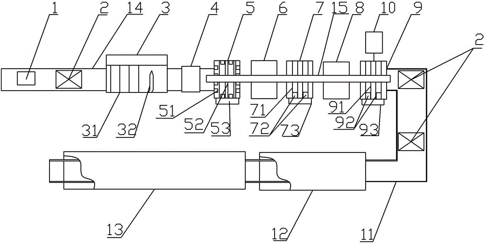
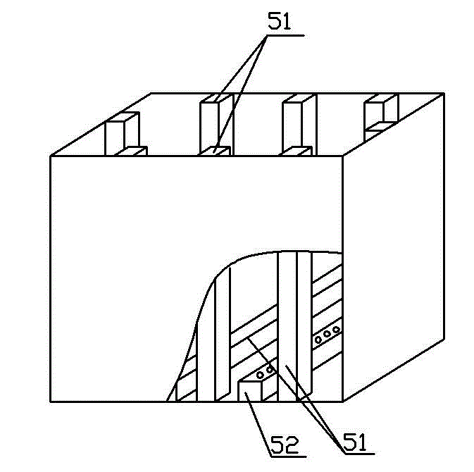
[0035] A waste flue gas denitrification catalyst regeneration equipment, such as Figure 1~3As shown, it includes crawler belt conveying device 14, spray cleaning device 3, ultrasonic cleaning tank 5, deionized water cleaning device 6, pickling tank 7, draining basket 8, activation tank 9, rail conveying device 11, tunnel type Drying furnace 12 and tunnel-type calciner 13, a hoisting adjustment area 4 is also provided between the spray cleaning device 3 and the ultrasonic cleaning tank, and a hoisting device 15 is provided between the end of the rail conveying device 14 and the front end of the rail conveying device 11. The device 11 passes through a tunnel drying furnace 12 and a tunnel calciner 13 .

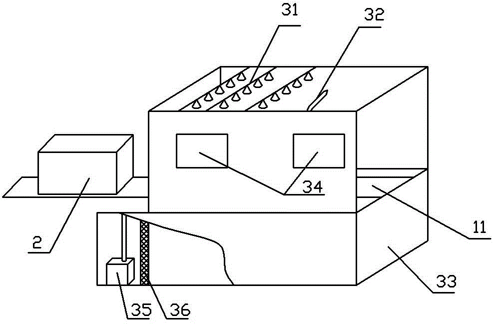
[0036] A mobile vacuum cleaner 1 is arranged above the front section of the crawler conveyor 14, and the rear section of the crawler conveyor 14 passes through a spray cleaning device 3, and the spray cleaning device 3 includes a sprayer 31 and a high-pressure water gun located...

Embodiment 2

[0051] Adopt the equipment identical with embodiment 1 to carry out regeneration treatment to the SCR denitration catalyst module identical with embodiment 1 specification, comprise the following steps:

[0052] (1) Place the catalyst module 2 on the crawler belt conveyor, use the mobile industrial vacuum cleaner 1 to absorb and remove dust from the catalyst module 2 under negative pressure, and perform artificial through-holes and drilling to remove dust alternately to improve the effect of dust removal;

[0053] (2) Spray cleaning and high-pressure spray gun cleaning: move the catalyst module 2 after dust removal to the spray cleaning device 3 along the crawler conveyor device 14, and first use the cleaning liquid with a spray pressure of 1.3Mpa to pass through the spray cleaning device After the sprayer 31 of 3 cleans the catalyst module 2 on a large area for 5 minutes, then adopts the high-pressure spray gun 32 to manually clean the catalyst module 5 minutes on a point-to-p...

Embodiment 3

[0059] Adopt the equipment identical with embodiment 1 to carry out regeneration treatment to the SCR denitration catalyst module identical with embodiment 1 specification, comprise the following steps:

[0060] (1) Place the catalyst module 2 on the crawler belt conveyor, use the mobile industrial vacuum cleaner 1 to absorb and remove dust from the catalyst module 2 under negative pressure, and perform artificial through-holes and drilling to remove dust alternately to improve the effect of dust removal;

[0061] (2) Spray cleaning and high-pressure spray gun cleaning: move the catalyst module 2 after dust removal to the spray cleaning device 3 along the crawler conveyor device 14, and first use the cleaning liquid with a spray pressure of 0.5Mpa to pass through the spray cleaning device 3. After the sprayer 31 of 3 cleans the catalyst module in a large area for 40 minutes, then use the high-pressure spray gun 32 to manually clean the catalyst module for 40 minutes. The weight...


PUM


Abstract

The invention discloses a waste flue gas denitration catalyst regeneration method, and belongs to the field of air pollution control. The method comprises the following steps: (1) removing dust through vacuum adsorption; (2) spray-cleaning and cleaning using a high-pressure spray gun; (3) washing with deionized water after ultrasonic cleaning; (4) draining off after acid pickling; (5) soaking with an activation solution, wherein the activation solution is an aqueous solution of a precursor of V2O5-WO3 or V2O5-MoO3, the weight percentage of metal oxides in the V2O5-WO3 activation solution is as follows: 0.8-5.0% of V2O5, 0.3-1.0% WO3 and the balance of water, the weight percentage of metal oxides in the V2O5-MoO3 activation solution is as follows: 0.8-5.0% of V2O5, 0.15-1.0% of MoO3 and the balance of water; (6) drying and calcining. The invention also discloses waste flue gas denitration catalyst regeneration equipment which includes a tracked conveying device, a spray cleaning device, an ultrasonic cleaning tank, a deionized water cleaning device, a pickling tank, a drain basket, an activation tank, a rail transport device, a tunnel kiln and a tunnel calciner, which are sequentially arranged.

Description

technical field [0001] The invention belongs to the field of air pollution control, and in particular relates to a method and equipment for regenerating a waste flue gas denitrification catalyst. Background technique [0002] Nitrogen oxides are one of the main air pollutants. Nitrogen oxides can form acid rain, photochemical smog, etc. Now the nationwide smog has a lot to do with nitrogen oxides. Coal-fired flue gas emissions from thermal power plants are the main source of anthropogenic nitrogen oxides. NO X The emission concentration is the most stringent control standard in the world (100mg / m 3 ). [0003] In order to control the emission of nitrogen oxides, SCR (Selective Catalytic Reduction) denitrification catalysts, that is, waste flue gas denitrification catalysts, are widely installed and used in the renovation of old thermal power plants and the construction of new thermal power plants to reduce the emission of nitrogen oxides. The SCR denitration catalyst has...

Claims


Application Information

Patent Timeline
Patent Type & Authority Applications(China)
IPC IPC(8): B01J38/52B01J38/60B01J38/48B01D53/56B01D53/86B01D53/96
Inventor 李志成严亮刘磊朱旭宾
Owner 河南博苑新未来环保科技有限公司
Why Eureka
Try Eureka