Combined layout structure of four-outlet double-row rear flue air system with flue gas waste heat recovery device

A recovery device and flue gas waste heat technology, applied in the direction of air induction, greenhouse gas reduction, climate sustainability, etc., can solve the problems of long flue, large layout, large flue resistance, etc. Less power consumption, reduced factory power consumption, and uniform smoke flow field

Active Publication Date: 2018-01-26
CHINA ENERGY ENG GRP GUANGDONG ELECTRIC POWER DESIGN INST CO LTD
View PDF8 Cites 0 Cited by
  • Summary
  • Abstract
  • Description
  • Claims
  • Application Information

AI Technical Summary

Problems solved by technology

[0005] The purpose of the present invention is to provide a four-outlet exhaust system with a flue gas waste heat recovery device to solve the technical problems of the existing coal-fired thermal power plant, such as the arrangement of equipment after the dust collector, which occupies a large area, the flue is long, and the flue resistance is large. Combined layout structure of double-row rear flue gas system

Method used


Image

  • Combined layout structure of four-outlet double-row rear flue air system with flue gas waste heat recovery device
  • Combined layout structure of four-outlet double-row rear flue air system with flue gas waste heat recovery device
  • Combined layout structure of four-outlet double-row rear flue air system with flue gas waste heat recovery device

Examples


Embodiment 1

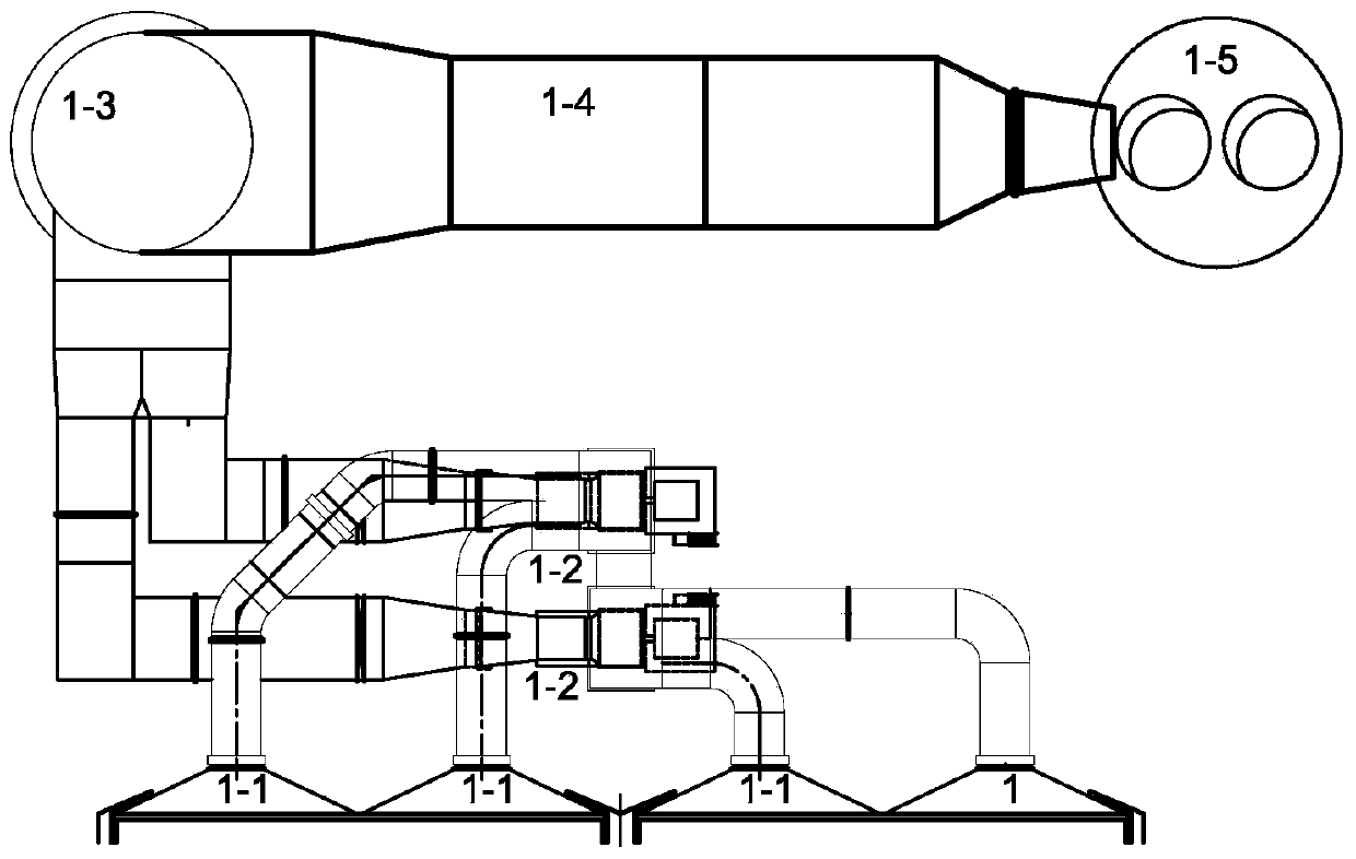
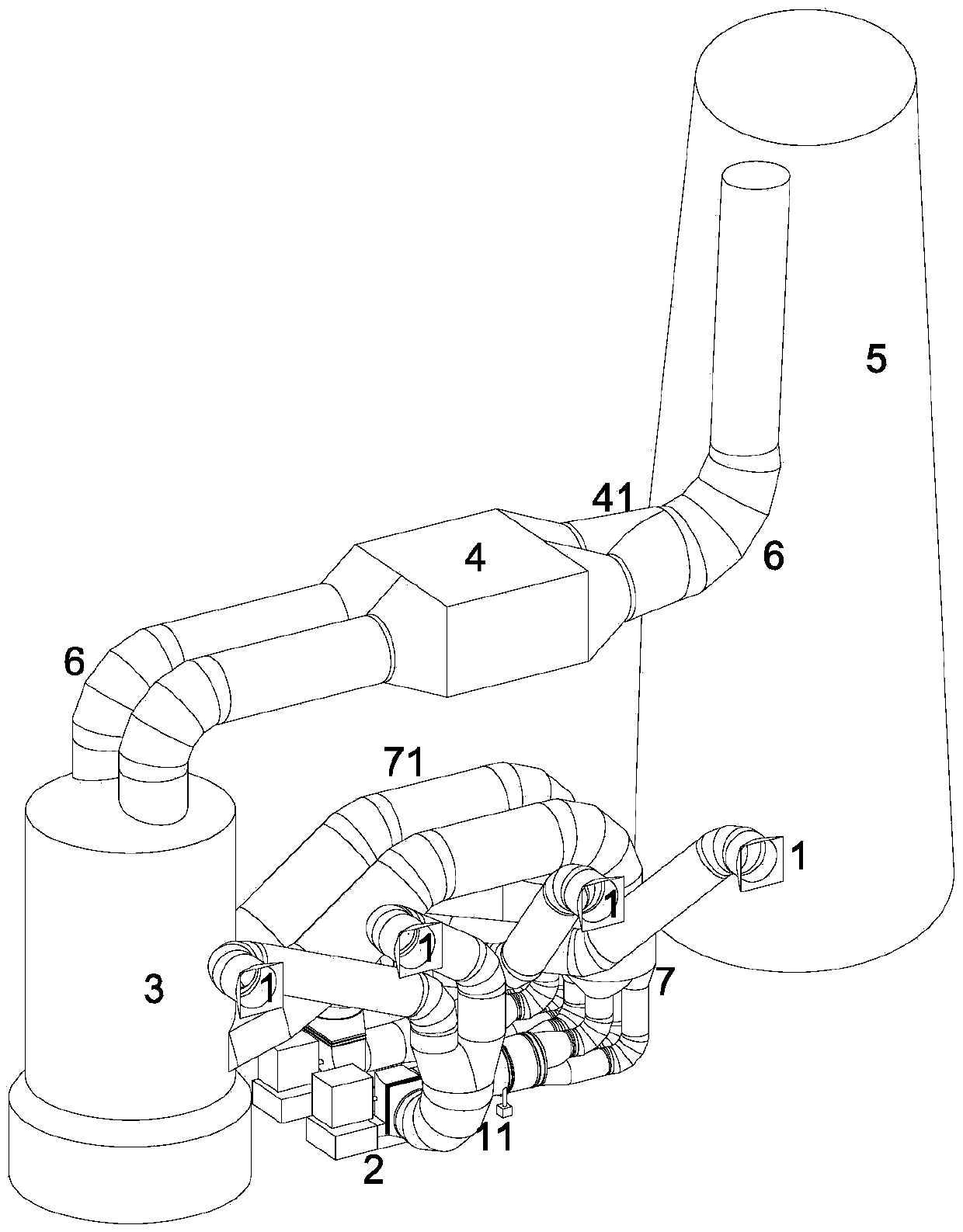
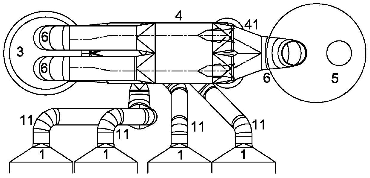
[0029] refer to Figure 2 to Figure 4 As shown, the combined layout structure of the four-outlet double-row rear flue air system with flue gas waste heat recovery device includes four dust collector outlets 1, induced draft fan structure, desulfurization absorption tower 3, wet electrostatic precipitator structure and chimney 5, and induced draft fan structure It is a double row induced draft fan structure composed of two induced draft fans 2, the air inlet of each induced draft fan 2 is connected to two dust collector outlets 1, and the two induced draft fans 2 are connected to the desulfurization absorption tower 3 through the flue gas waste heat recovery device 7 The wet electrostatic precipitator structure is composed of a wet electrostatic precipitator 4, the two air outlets of the desulfurization absorption tower 3 are respectively connected to the two air inlets of a wet electrostatic precipitator 4, and the two air outlets of the wet electrostatic precipitator 4 The ai...


PUM


Abstract

The invention relates to a four-outlet biserial rear smoke wind system combined layout structure with a flue gas waste heat recovery device. The four-outlet biserial rear smoke wind system combined layout structure comprises four dust catcher outlets, a draught fan structure, a desulfurizing absorption tower, a wet type Electrostatic precipitator structure and a chimney; the draught fan structure is a biserial draught fan structure composed of two draught fans, an air inlet of each draught fan is communicated with the two corresponding dust catcher outlets, and the two draught fans are connected with an air inlet of the desulfurizing absorption tower through the flue gas waste heat recovery device; the wet type Electrostatic precipitator structure is made of a wet type Electrostatic precipitator, two air outlets of the desulfurizing absorption tower are connected with two air inlets of the wet type Electrostatic precipitator, and two air outlets of the wet type Electrostatic precipitator are connected with an air inlet of the chimney through a collecting pipe; and the draught fan structure, the flue gas waste heat recovery device and the four dust catcher outlets are disposed between the desulfurizing absorption tower and the chimney, the draught fan structure and the flue gas waste heat recovery device are located below the four dust catcher outlets, and the wet type Electrostatic precipitator structure is located over the four dust catcher outlets. The four-outlet biserial rear smoke wind system combined layout structure has the advantages of the less occupied area, initial investment cost reduction and the like, and also has the effects of efficient operation, energy conservation and the like.

Description

technical field [0001] The invention relates to a combined layout structure of a four-outlet double-row rear flue air system with a flue gas waste heat recovery device. The utility model belongs to the technical field of smoke exhaust and ventilation equipment in power plants. Background technique [0002] In a coal-fired thermal power plant project, the distance from the dust collector and induced draft fan to the center line of the chimney is one of the important land occupation indicators. Most of the equipment in the flue gas system is arranged behind the furnace, while the front flue and dust collector are relatively fixed. , the optimization of the rear layout of the furnace is mainly concentrated after the dust collector. For the layout form after the dust collector, the main layout pattern at home and abroad basically adopts the arrangement of each equipment in a row. The induced draft fan 1-2 is arranged after the dust collector 1-1, and the desulfurization absorpt...

Claims


Application Information

Patent Timeline
Patent Type & Authority Patents(China)
IPC IPC(8): F23J15/00F23J15/02F23J15/06F23L17/00
CPCY02E20/30
Inventor 杨劲印佳敏马雪松潘灏邓宏伟范旭谭灿燊梁展鹏蔡春荣
Owner CHINA ENERGY ENG GRP GUANGDONG ELECTRIC POWER DESIGN INST CO LTD
Why Eureka
Try Eureka