Low-profile dual-polarized base station antenna

A base station antenna and dual-polarization technology, applied in the field of antennas and mobile communication base station antennas, can solve the problems of unfavorable miniaturization, high profile of dual-polarized base station antennas, and large size of reflectors, so as to increase integration and reduce size. , the effect of reducing the section height

Active Publication Date: 2015-09-09
XIDIAN UNIV
View PDF6 Cites 33 Cited by
  • Summary
  • Abstract
  • Description
  • Claims
  • Application Information

AI Technical Summary

Problems solved by technology

[0004] The purpose of the present invention is to overcome the defects of the above-mentioned existing base station antennas, and propose a low-profile dual-polarization base station antenna,

Method used


Image

  • Low-profile dual-polarized base station antenna
  • Low-profile dual-polarized base station antenna
  • Low-profile dual-polarized base station antenna

Examples


Embodiment 1

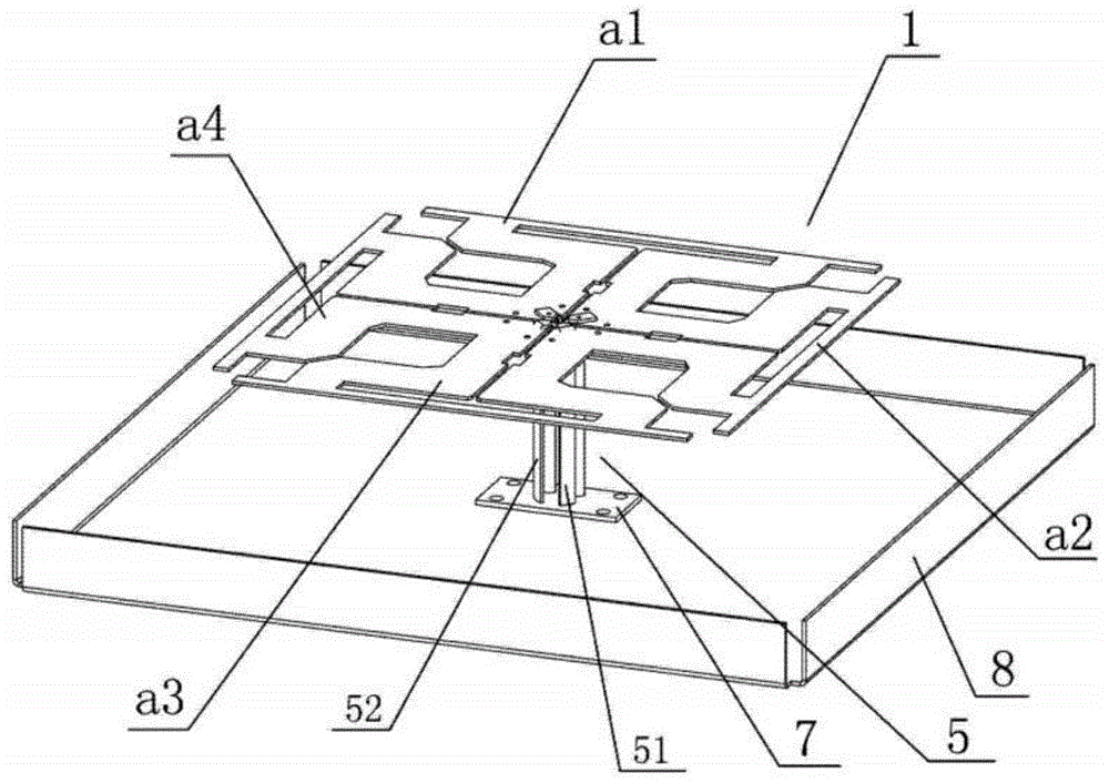
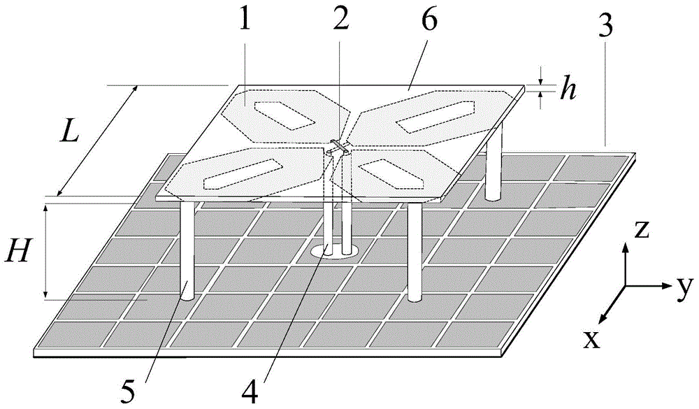
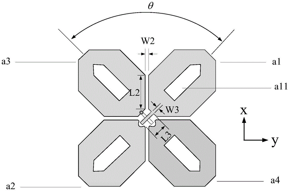
[0024] refer to figure 2 , the present invention includes a ±45° dual-polarized planar vibrator 1, a ±45° planar feed probe 2, an artificial magnetic conductor reflector 3, a coaxial line 4, a support column 5 and a dielectric material plate 6; the dielectric material plate 6 adopts The Rogers 5880 material with a dielectric constant of 2.2 has a square surface shape, its side length L is 37.4mm, and its thickness h is 0.508mm. There are metallized through holes on its +45° angle bisector; on this dielectric material plate The upper surface of the 6 is printed with a +45° planar feed probe, and the lower surface is printed with a -45° planar feed probe and a ±45° dual-polarized planar oscillator to achieve planarization and reduce the cost of large-scale processing. Cost; the artificial magnetic conductor reflector 3 is composed of an upper layer patch, a middle medium and a lower floor, and a feeding through hole is arranged in the center thereof, and the artificial magnetic...

Embodiment 2

[0028] Embodiment 2 has the same structure as Embodiment 1, and only the following parameters are modified: the side length L4=14mm of the square patch, the distance g1=1mm between adjacent square patches, the order N=6 of the square patch array, the feeding The length of the probe is L3=4mm, the width W3=0.5mm, the distance between the lower surface of the dielectric material plate and the upper surface of the artificial magnetic conductor reflection plate is H=10mm, and the thickness of the reflective medium plate is h1=4.5mm.

Embodiment 3

[0030] Embodiment 3 has the same structure as Embodiment 1, only the following parameters are modified: the side length L4 of the square patch = 17mm, the distance between adjacent square patches g1 = 1.2mm, the order of the square patch array N = 8, and the plane The length L3 of the feeding probe = 4.5mm, the width W3 = 1mm, the distance between the lower surface of the dielectric material plate and the upper surface of the artificial magnetic conductor reflection plate H = 11mm, and the thickness h1 of the reflective medium plate = 5.5mm.

[0031] Advantage of the present invention can be further illustrated by the simulation result of embodiment 1:

[0032] 1. Simulation content

[0033] The above-mentioned embodiment 1 is simulated by using the simulation software HFSS. Its port reflection coefficient and isolation are as Figure 5 As shown; when the +45° vibrator is fed by a single port, the horizontal plane far-field radiation pattern at the two frequency points of 2....


PUM

PropertyMeasurementUnit
Thicknessaaaaaaaaaa
Side lengthaaaaaaaaaa
Thicknessaaaaaaaaaa

Abstract

The invention discloses a low-profile dual-polarized base station antenna for solving the problems of high profile and large reflector size of the existing base station antenna. The low-profile dual-polarized base station antenna comprises a +/-45 DEG dual-polarized planar vibrator (1), a +/-45 DEG planar feed probe (2), an artificial magnetic conductor reflector (3), a coaxial line (4), a strut (5) and a dielectric material plate (6); the +/-45 DEG planar feed probe is printed on the upper surface of the dielectric material plate (6), and a -45 DEG planar feed probe and the +/-45 DEG dual-polarized planar vibrator are printed on the lower surface of the dielectric material plate (6); the dielectric material plate (6) is fixed above the artificial magnetic conductor reflector (3) via the strut (5), and the artificial magnetic conductor reflector (3) comprises a reflector dielectric plate (31), a square patch (32) and a floor (33); and the coaxial line (4) is used for exciting the antenna. The low-profile dual-polarized base station antenna has the characteristics of low profile and small reflector size, and is suitable for serving as a mobile communication base station antenna.

Description

technical field [0001] The invention belongs to the technical field of antennas, and relates to a dual-polarized base station antenna, in particular to a low-profile dual-polarized base station antenna based on an artificial magnetic conductor reflector, which can be applied to the field of mobile communication base station antennas. Background technique [0002] Mobile communication technology has brought fast information communication to human beings, and at the same time, the increase in demand has also promoted the vigorous development of mobile communication technology. The first-generation analog mobile communication system gradually faded out of our field of vision, the second-generation digital mobile communication system is in the ascendant, and then the third-generation broadband mobile communication system is being built worldwide. The fourth-generation mobile communication technology is being tested and Construction is also in full swing. In recent years, in ord...

Claims


Application Information

Patent Timeline
IPC IPC(8): H01Q1/38H01Q1/50H01Q15/14H01Q19/10H01Q21/24
Inventor 刘英王玖周艳民龚书喜
Owner XIDIAN UNIV
Why Eureka
Try Eureka