Vibration device

A technology of vibration device and driving part, which is applied to electromechanical devices, fluids using vibration, electrical components, etc., can solve problems such as shortening the life of the motor, and achieve the effect of maintaining the resonance frequency, reducing the production process and making the resonance frequency uniform.

Inactive Publication Date: 2015-09-09
SHENZHEN LINKCONN ELECTRONICS
View PDF8 Cites 3 Cited by
  • Summary
  • Abstract
  • Description
  • Claims
  • Application Information

AI Technical Summary

Problems solved by technology

When the motor rotates, when the brush passes through the gap between the magnet (segment) of the rectifier and the magnet, mechanical friction and electric spark (spark) are induced, thereby causing the brush and the commutator to be worn, thereby shortening the life of the motor

Method used


Image

  • Vibration device
  • Vibration device
  • Vibration device

Examples


Embodiment Construction

[0029] Hereinafter, embodiments of the present invention will be described in detail with reference to the drawings. During the description, the size and shape of the components shown in the drawings may be exaggerated for clearer and simpler description. In addition, in consideration of the structure and operation of the present invention, specifically defined terms may vary depending on the user's and operator's intention or practice. The definitions of these terms should be based on the overall content of the present specification.

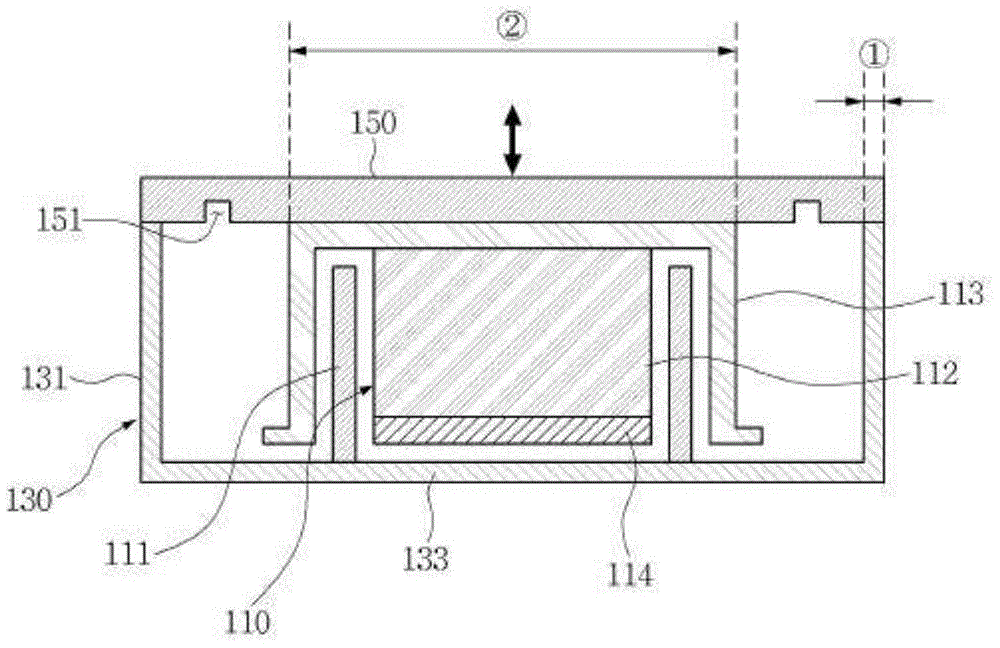
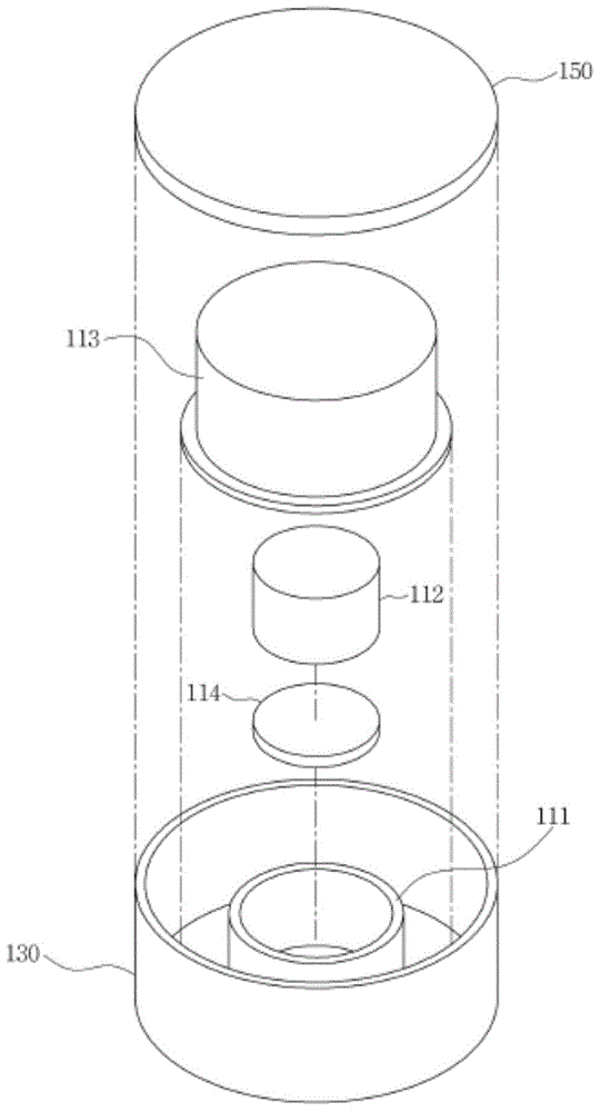
[0030] figure 1 It is a schematic diagram of the vibration device of the present invention. figure 1 A cross-sectional view of a vibration device is disclosed in . figure 2 It is an exploded perspective view of the vibration device of the present invention.

[0031] The vibration device shown in the figure may include a driving part 110 , a box part 130 , and a cover part 150 .

[0032] The driving part 110 may include a first part 111 an...


PUM


Abstract

The invention relates o a vibration device including a driving part in which a first member and a second member are relatively moved; a box part provided with the first member; and a cover part integrating a leaf spring into a whole, covering the box part, and provided with the second member. The over part includes elastic plastic. The vibration of the cover part can be realized by the drive of the driving part.

Description

technical field [0001] The present invention relates to a vibrating device which relies on linear motion to generate vibration. Background technique [0002] In general, the signal receiving function is one of the functions that communication instruments must have. And this kind of signal receiving function uses more types to have the sound function such as music or ring tone and the vibration function that makes the instrument vibrate. [0003] Among them, the vibration function is a function that is mainly used to avoid disturbing others when music or ringtones are emitted to the outside through the speaker. In order to realize this kind of vibration, a small vibration motor is usually driven, so that the driving force is transmitted to the case of the instrument, so that the instrument can vibrate. [0004] Vibration motors currently used in mobile phones can be divided into thinner flat type (coin type) and elongated bar type (bar type) according to their shape. [00...

Claims


Application Information

Patent Timeline
IPC IPC(8): H02K33/02H02K33/18
CPCB06B1/04H02K33/02
Inventor 王涧鸣
Owner SHENZHEN LINKCONN ELECTRONICS
Why Eureka
Try Eureka