Zero power consumption touch switch module circuit

A technology of touch switch and zero power consumption, which is applied in the field of zero power consumption touch switch module circuit, can solve the problems of large power consumption, achieve low cost, good application effect, and reduce the cost of use

Active Publication Date: 2017-09-29
LUAN TONGXIN CHANGNENG ELECTRONICS TECH CO LTD
View PDF5 Cites 0 Cited by
  • Summary
  • Abstract
  • Description
  • Claims
  • Application Information

AI Technical Summary

Problems solved by technology

[0002] The current electronic products or household appliances are in the standby state when they are not in normal use, but the controller circuit inside the appliance is consuming power, and the power consumption is also very large for a long time in the standby state

Method used


Image

  • Zero power consumption touch switch module circuit

Examples


Embodiment Construction

[0012] In order to make the technical means, creative features, goals and effects achieved by the present invention easy to understand, the present invention will be further described below in conjunction with specific illustrations.

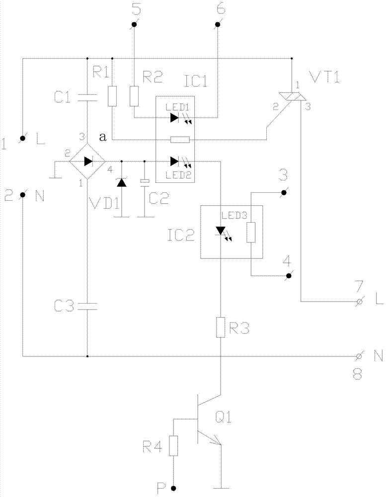
[0013] Such as figure 1 As shown, this zero-power consumption touch switch module circuit is used in electronic products, and the button switch and touch switch are used to turn on and off the switch of the electric appliance.

[0014] First, connect pin 5 to the +5V power supply of the electrical appliance used, pin 6 to the CPU control switch signal control terminal of the electrical appliance, and use low level as the power-on signal. At the same time, connect pin 3 and pin 4 of the IC2 optocoupler to the switch control terminal of the controlled electrical appliance, connect pin 1 to the input end of the 220V power supply input, and connect pin 7 to the input end of the 220V power supply input of the controlled electrical appliance, and turn...


PUM


Abstract

The present invention discloses a zero power consumption touch switch module circuit which is applied to an electronic product. A button switch and a touch switch are used to turn on and turn off a switch of an electrical appliance. In a state that the electrical appliance is turned off, zero power consumption standby of the electrical appliance is achieved. A fifth pin is connected to a +5V power supply of the electrical appliance, and a sixth pin is connected to a CPU control startup and shutdown signal controlling terminal, wherein the low level is used as a startup signal. A third pin and a fourth pin of an optical coupler IC2 are connected to startup and shutdown controlling terminals of the controlled electrical appliance. A first pin is connected to a power supply input end of a 220V power supply, and a seventh pin is connected to one end of a 220V power input of the controlled electrical appliance. After the 220V power supply is connected, the 220V voltage at the L end of the first pin is divided into two paths. One path of the voltage supplies power to a first pin of a bidirectional triode thyristor VT1. The other path of the voltage is connected to a bridge rectifier diode a via a capacitor C1, and the voltage is stepped down by the capacitor C1, rectified by the bridge rectifier diode a, stabilized by a voltage-regulator diode VD1 and filtered by a capacitor C2, and then a 9V voltage is output for powering interior luminescent tubes of an optical coupler IC1 and the optical coupler IC2.

Description

technical field [0001] The invention relates to the field of lighting technology, in particular to a zero-power consumption touch switch module circuit. Background technique [0002] The current electronic products or household appliances are in the standby state when they are not in normal use, but the controller circuit inside the appliance is consuming power, and the power consumption is also very large in the standby state for a long time. Contents of the invention [0003] The technical problem to be solved by the present invention is to provide a simple, economical and environment-friendly zero-power consumption touch switch module circuit. [0004] The technical problem to be solved by the present invention adopts the following technical solutions to realize: [0005] A zero-power consumption touch switch module circuit, comprising a first capacitor C1, a first resistor R1, a second resistor R2, a first optocoupler IC1, a triac VT1, a bridge rectifier diode a, a th...

Claims


Application Information

Patent Timeline
Patent Type & Authority Patents(China)
IPC IPC(8): H03K17/96H03K17/72H03K17/78
Inventor 刘举柱
Owner LUAN TONGXIN CHANGNENG ELECTRONICS TECH CO LTD
Why Eureka
Try Eureka