
Two-stage membrane method oil-gas recovery apparatus and recovery method thereof

An oil and gas, membrane technology, applied in the field of two-stage membrane oil and gas recovery devices, can solve the problems of reducing equipment reliability and ease of use, unable to effectively ensure that the emission concentration meets the requirements of the national standard, increasing process complexity and danger, etc.

Inactive Publication Date: 2015-09-16
CHINA PETROLEUM & CHEM CORP +1
View PDF3 Cites 6 Cited by
  • Summary
  • Abstract
  • Description
  • Claims
  • Application Information

AI Technical Summary

Problems solved by technology

[0004] According to the glass transition temperature Tg, gas separation membranes can be divided into rubbery polymers (Tg room temperature). It is a rubbery oil-gas separation membrane, mainly PDMS (polydimethylsiloxane) and POMS (polymethyloctylsiloxane). It is impossible to effectively ensure that the emission concentration meets the national standard. In order to ensure that the emission meets the standard, it is often necessary to add a small activated carbon adsorption device at the back end. Since the activated carbon needs regular vacuum desorption, and there is a temperature rise during the adsorption process, the complexity and complexity of the process are greatly increased. Hazards that reduce device reliability and ease of use

Method used


Image

  • Two-stage membrane method oil-gas recovery apparatus and recovery method thereof

Examples


Embodiment Construction

[0020] The present invention proposes a two-stage membrane oil gas recovery device and its recovery method. In order to make the advantages and technical solutions of the present invention clearer and clearer, the present invention will be further clearly and completely described in conjunction with specific examples below.

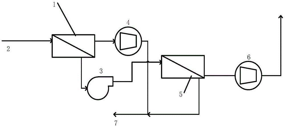
[0021] Such as figure 1 As shown, a two-stage membrane method oil and gas recovery device, which specifically includes a rubber membrane module 1, on one side of the rubber membrane module 1 is the inlet port 2 of the rubber membrane module, and in the pipeline connected to the inlet port 2 A micro-pressure sensor can be preferably arranged on the top, and when it is detected that the pressure in the oil storage tank connected with the pipeline is higher than the set value, the device is opened to allow oil and gas to enter the oil and gas recovery device of the present invention.

[0022] The oil and gas first enter the rubber state membrane module 2, an...


PUM


Abstract

The present invention discloses a two-stage membrane method oil-gas recovery apparatus and a recovery method thereof. The two-stage membrane method oil-gas recovery apparatus comprises a rubber state membrane assembly, a glass state membrane assembly, a vacuum pump 1 and a vacuum pump 2, wherein the inlet end of the rubber state membrane assembly is communicated with an oil-gas inlet pipeline, the retentate side outlet end of the rubber state membrane assembly is connected with the inlet end of a fan through a pipeline, the outlet end of the fan is connected with the inlet end of the glass state membrane assembly, the retentate side outlet end of the glass state membrane assembly is connected with the vacuum pump 2, standard discharge is performed after passing through the vacuum pump 2, the retentate side outlet end of the rubber state membrane assembly is connected with the vacuum pump 1, the vacuum pump 1 is connected with an absorption tower or oil tank, and the retentate side of the glass state membrane assembly is connected to the absorption tower or oil tank through a pipeline. Compared with the traditional rubber state membrane separation and active carbon adsorption process scheme, the apparatus and the method of the present invention have the following advantages that: high reliability and high safety are provided, the structure is delicate, the occupation area is small, and no secondary pollution is generated.

Description

technical field [0001] The invention belongs to the technical field of environmental protection, and in particular relates to a two-stage membrane oil gas recovery device and a recovery method thereof. Background technique [0002] In recent years, with the continuous increase of the number of automobiles in our country, the consumption of refined oil has risen rapidly, and the organic gas pollutants discharged into the atmosphere during the storage, transportation and sales of gasoline have gradually attracted people's attention. In 2007, the national The State Environmental Protection Administration has issued GB20950 "Emission Standards of Air Pollutants for Oil Storage Depots" and GB20952 "Emission Standards for Air Pollutants for Gas Stations", requiring all oil storage depots and gas stations to complete oil and gas recovery transformation before the specified time. Traditional oil and gas recovery methods mainly include absorption method, adsorption method, membrane s...

Claims


Application Information

Patent Timeline
IPC IPC(8): B01D53/22B01D53/18
Inventor 王振中张卫华修德欣丁莉丽蒲鹤王洁吴锋棒
Owner CHINA PETROLEUM & CHEM CORP
Learn More