Compound vertical-type milling machine

A vertical milling machine and duplex technology, applied in the direction of milling machines, milling machine equipment, large fixed members, etc., can solve problems such as insufficient rigidity, inability to choose the best working height, and unstable processing quality, so as to shorten the empty travel distance and improve the machine tool function. Humanized, easy-to-digital control effects

Inactive Publication Date: 2015-09-16
云南锦润数控机械制造有限责任公司
View PDF5 Cites 7 Cited by
  • Summary
  • Abstract
  • Description
  • Claims
  • Application Information

AI Technical Summary

Problems solved by technology

The disadvantages are: the Z-direction feed stroke of the spindle is short (generally no more than 150mm), poor guiding, insufficient rigidity, unstable processing quality, and difficult to achieve high spindle speed and high-precision machining
The disadvantages are: because the cutting force and reaction force intersect on the mounting surface of the column and the bed, the strength requirements are high, so the size of the bed is large; and because the Y-guided guide rail is on the bed, the bed becomes a large and complex part , heavy weight, high manufacturing and processing costs
In addition, due to the fixed height of the workbench, the best working height cannot be selected, it is inconvenient for workers to operate, and the coordination between man and machine is poor.

Method used


Image

  • Compound vertical-type milling machine
  • Compound vertical-type milling machine
  • Compound vertical-type milling machine

Examples


Embodiment Construction

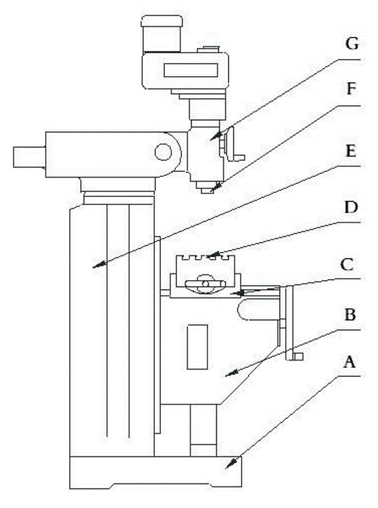
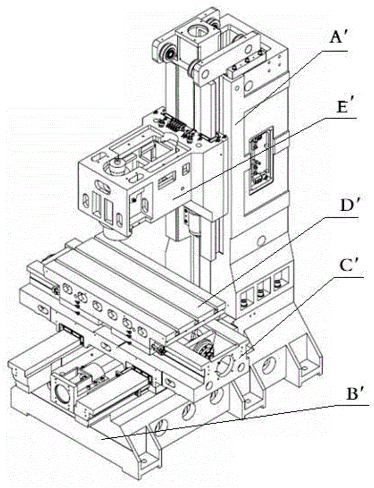
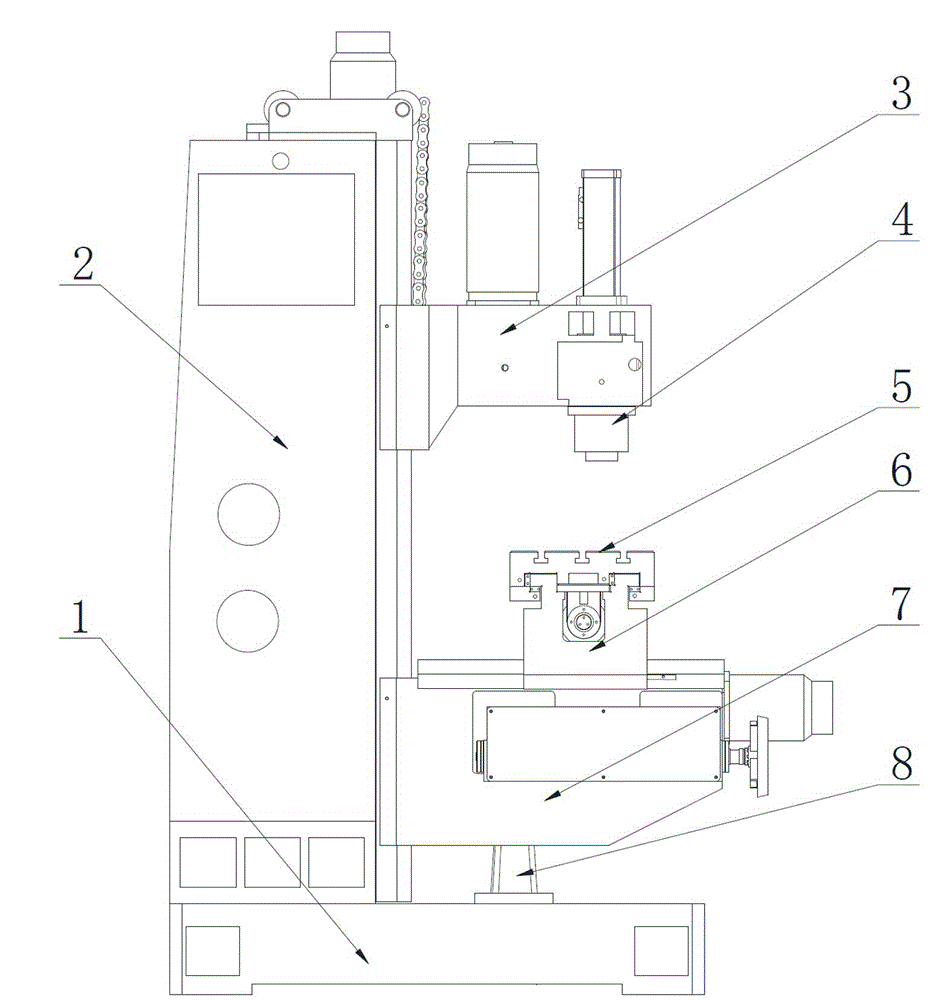
[0011] Such as image 3 Shown, the present invention mainly is made up of base 1, column 2, main shaft box 3, main shaft 4, workbench 5, sliding saddle 6, lifting table 7, screw mandrel nut pair 8, control system. The column 2 is fixedly installed on the base 1 of the machine tool. The workbench 5 is fitted on the guide rail of the saddle 6 and can reciprocate laterally (X direction) along the saddle. The saddle 6 is fitted on the guide rail of the lifting platform 7 and can reciprocate longitudinally (Y direction) along the lifting platform. The inner side of the lifting platform 7 is connected to the column 2 through the column guide rail, and the bottom is supported on the base 1 through the screw nut pair 8, and the height (Z direction) position of the lifting platform can be adjusted through the screw. The main shaft 4 is installed in the spindle box 3 to form the milling head part, and the inner side of the whole milling head part is fitted on the column guide rail and...


PUM


Abstract

The invention discloses a compound vertical-type milling machine. The compound vertical-type milling machine comprises a base (1), a stand column (2), a main shaft box (3), a main shaft (4), a working bench (5), a saddle (6), a lifting platform (7), a screw-nut pair (8) and a numerical control system. The stand column (2) is fixedly installed on the base (1). The working bench (5) is assembled to a guide rail of the saddle (6) and can carry out traverse reciprocating motion along the saddle. The saddle (6) is assembled to a guide rail of the lifting platform (7) and can carry out vertical reciprocating motion along the lifting platform. The compound vertical-type milling machine is a novel structure compound vertical-type milling machine with high motion rigidity and high rotation rate.

Description

technical field [0001] The invention belongs to the technical field of vertical milling machine structures. Background technique [0002] At present, vertical milling machines are mainly divided into two categories: lifting table vertical milling machines (including rocker arm milling machines) and bed type vertical milling machines. Lift table milling machine such as figure 1 As shown, the workbench E is installed on the guide rail of the sliding saddle C to realize the horizontal (X direction) movement, the sliding saddle C is installed on the guide rail of the lifting platform B to realize the longitudinal (Y direction) movement, and the lifting platform B is on the up and down of the guide rail of the column E Movement (Z-direction movement), but this is not Z-direction work feed movement, its Z-direction work feed movement is realized by the spindle F moving up and down in the headstock G (the headstock cannot move up and down). Its advantages are: the action ...

Claims


Application Information

Patent Timeline
Patent Type & Authority Applications(China)
IPC IPC(8): B23C1/06B23Q1/62B23Q5/40B23Q1/58
CPCB23C1/06B23Q1/585B23Q1/621B23Q5/402
Inventor 杨石林张春发李再参张峰张拯华徐敏浦宏毅罗庆丰杨圆圆房巧红张亚兴段海莲徐爱梅
Owner 云南锦润数控机械制造有限责任公司
Why Eureka
Try Eureka