Device and method for preparing spherical cavitation bubble
A cavitation, spherical technology
- Summary
- Abstract
- Description
- Claims
- Application Information
AI Technical Summary
Problems solved by technology
Method used
Image
Examples
preparation example Construction
[0037] The device for preparing spherical cavities according to the present invention:
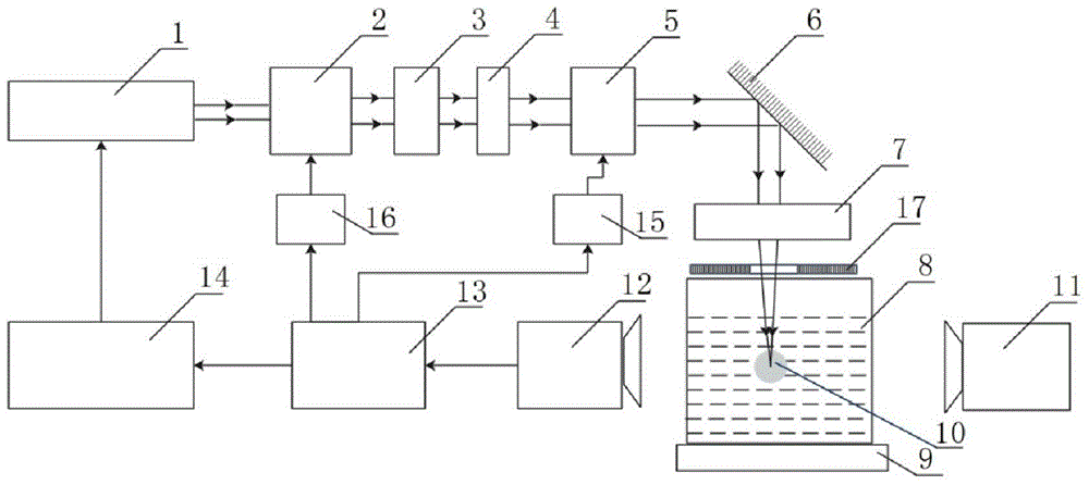
[0038] like figure 1 As shown, the pulsed laser 1 emits a pulsed laser beam with a Gaussian beam shape, which provides excitation energy for the generation of spherical cavitation. The laser spot is circular and the pulse width is less than 100 ns. The output power density J of the laser is much larger than that of the liquid medium laser Breakdown Threshold Power Density J 0 ; The adjustable beam expander system 2 receives the pulsed laser emitted by the pulsed laser, amplifies the spot of the laser, and controls the magnification by the adjustable beam expander control system 7, and the magnification β of the adjustable beam expander system is determined by the device on the optical path Determined by the minimum aperture diameter D, value range Where d is the output laser spot diameter of the pulse laser; the amplified laser is converted into linearly polarized light through a linear...
Embodiment 1
[0058] 1) The liquid medium is tap water.
[0059] 2) The pulsed laser 1 is SpitLight1000 pulsed Nd:YAG laser, which outputs 1064nm infrared pulsed Gaussian laser beam, the laser pulse width is 10ns, the repetition frequency is 10Hz, the divergence angle is ≤0.7mrad, and the single pulse laser outputs a stable energy of 250mJ (according to the tap water Laser breakdown threshold 0.5×10 11 W / cm 2 And device loss, and leave the experimental measurement of the degree of redundancy). The output spot diameter is 5mm.
[0060] 3) The adjustable beam expander system adopts YAG laser high-performance beam expander, the model is EPZ-37C of GEOMATEC, first set the magnification of the beam expander system to 4 times. The diameter after beam expansion is 20 mm.
[0061] 4) The attenuation amplitude τ of the adjustable attenuator 0 Set to 10%.
[0062] 5) The focal length of the short focus system is 150mm.
[0063] 6) The distance between the aperture and the short focus system is...
Embodiment 2
[0072] 1) The liquid medium is silica gel, the single-pulse laser output stable energy is 800mJ, the adjustable beam expansion system is 4 times, and the rest of the operations are repeated from steps 1) to 9) of Example 1.
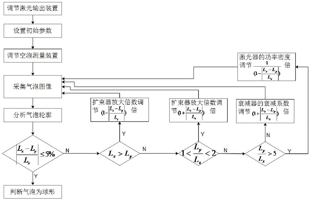
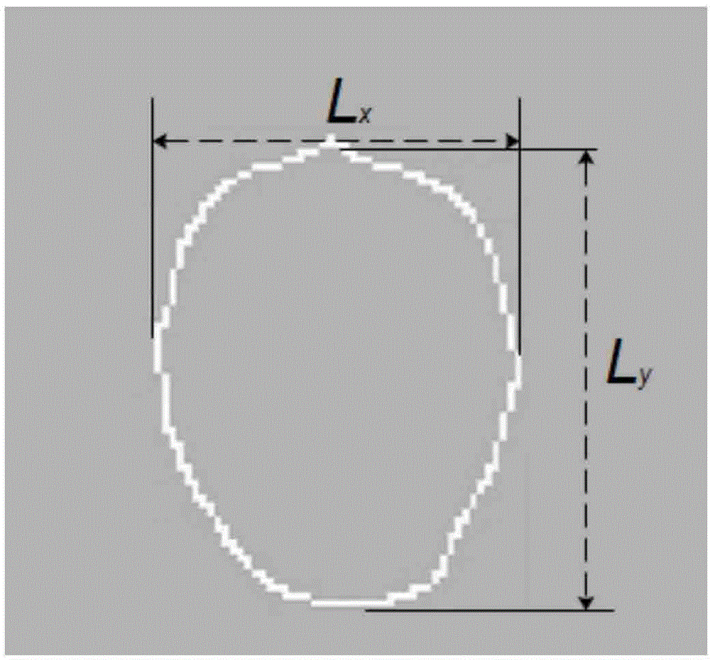
[0073] 2) Calculate the length L of the cavity in the x direction x = 1.56mm and the length L in the y direction y =8.52mm.
[0074] 3) because and Adjust the output energy of the laser to 135mJ.
[0075] 4) Collect the laser-induced cavitation image again.
[0076] 5) The length L of the cavity in the x direction at this time x = 1.16mm and the length L in the y direction y = 1.12 mm. therefore , laser-induced spherical cavitation was obtained.
PUM
| Property | Measurement | Unit |
|---|---|---|
| length | aaaaa | aaaaa |
| length | aaaaa | aaaaa |
| length | aaaaa | aaaaa |
Abstract
Description
Claims
Application Information
 - R&D
- Intellectual Property
- Life Sciences
- Materials
- Tech Scout
- Unparalleled Data Quality
- Higher Quality Content
- 60% Fewer Hallucinations
Browse by: Latest US Patents, China's latest patents, Technical Efficacy Thesaurus, Application Domain, Technology Topic, Popular Technical Reports.
© 2025 PatSnap. All rights reserved.Legal|Privacy policy|Modern Slavery Act Transparency Statement|Sitemap|About US| Contact US: help@patsnap.com


