Electric heating and heating device for automobile exhaust emission

A technology of automobile exhaust and heating device, which is applied in exhaust device, muffler device, air quality improvement and other directions, can solve the problem of complex structure of air guide and heat exchange tube system, low heating and heating speed of exhaust gas, and ineffective catalytic converter, etc. It can improve the effect of catalytic conversion, facilitate uniform heating, and reduce automobile exhaust pollution.

Active Publication Date: 2018-04-03
BEIJING GAOXIN GREAT FILTER CO LTD
View PDF6 Cites 0 Cited by
  • Summary
  • Abstract
  • Description
  • Claims
  • Application Information

AI Technical Summary

Problems solved by technology

[0002] Existing pollutant emission reduction technologies for controlling vehicle exhaust emissions all use exhaust catalytic treatment technology, that is, a catalytic converter is installed in the exhaust pipe of the vehicle, and the optimum operating temperature of the catalyst is above 250°C, otherwise it will reach No effect of catalytic conversion; in reality, the temperature of the exhaust gas is generally lower than 250°C when the car is cold-started, restarted after intermittent parking, and short-term parking, idling and light load conditions, and most of the catalysts do not work or have very little effect , therefore, causing widespread and massive exhaust pollution
[0003] In order to solve the problem that the catalytic converter does not work due to low-temperature exhaust emissions from automobiles, Chinese patent ZL201320895395·7 provides an automatic heating device for exhaust emissions of automobiles, which is installed before the catalytic converter. The disadvantages are: Due to the split combination of heat storage and heat exchanger and bypass pipeline, it takes up a lot of space. On the other hand, the structure of the gas guide and heat exchange pipe system is complex, difficult to manufacture, and prone to failure, and the heating rate of exhaust gas is low.

Method used


Image

  • Electric heating and heating device for automobile exhaust emission
  • Electric heating and heating device for automobile exhaust emission
  • Electric heating and heating device for automobile exhaust emission

Examples


Embodiment Construction

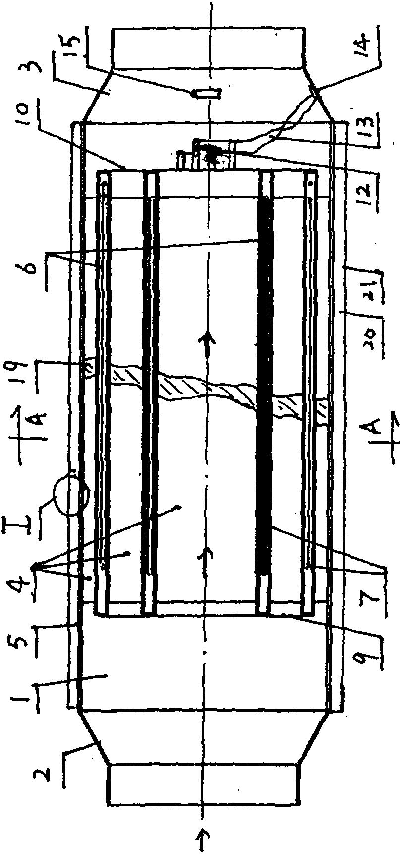
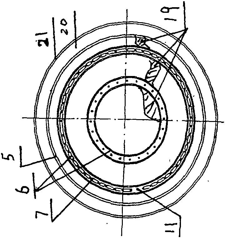
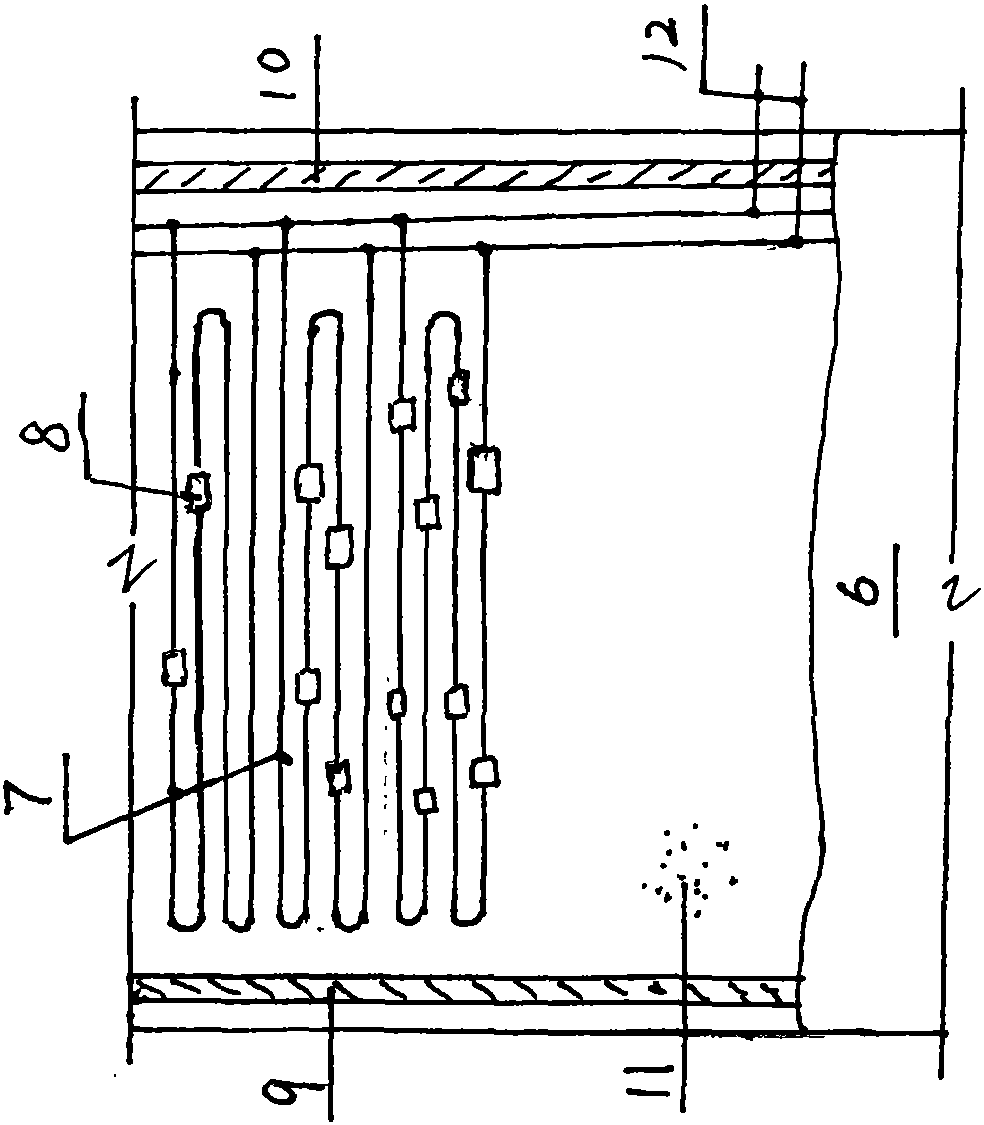
[0016] Further detailed description in conjunction with the accompanying drawings; the arrows in the figure indicate the flow direction of the exhaust gas.

[0017] Such as Figure 1-6 As shown, the electric heating and temperature-raising device for automobile exhaust emission has a housing with an outer heat insulation layer 20, an electric heater and an electric control mechanism; The left and right ports 2 and 3 of the exhaust gas on the top are composed; the main body 1 is composed of 2 to 8 air guiding cylinders 4 in turn from the outside to the inside, and each air guiding cylinder 4 is fixed with a honeycomb packing body 19; the outermost air guiding cylinder 4 is composed of the outer cylinder 5 and the outermost electric heater sleeve 6, the innermost air guide cylinder 4 is composed of the innermost electric heater sleeve 6, and the middle air guide cylinder 4 is composed of two corresponding adjacent electric heater sleeves. Composed of heater sleeves 6, the left ...


PUM


Abstract

The invention relates to an electrical heating device for vehicle exhaust emission, belongs to the technical field of vehicle exhaust pollutant emission reduction and aims to solve the problem of poor low-temperature exhaust catalytic conversion effects. A main body (1) is formed by a plurality of concentric gas guide cylinders (4) filled with cellular packing bodies (19), each gas guide cylinder (4) is formed by a corresponding electrical heater sleeve (6) or two adjacent electrical heater sleeves (6), electrical heating bodies (7) in regular distribution are fixedly mounted in each electrical heater sleeve (6) in a sealing insulation manner, a power outgoing line (12) is led out of each electrical heater sleeve (6) in a parallel connection manner and in a sealing insulation manner, and the electrical heating device further comprises a temperature controller (15). The electrical heating device for vehicle exhaust emission has the advantages that total electrical heating power is increased conveniently, uniform heating is benefitted and the size of the electrical heating device is decreased beneficially; after the electrical heating device and a catalytic converter are mounted together, heating speed of low-temperature exhaust can be increased uniformly and greatly particularly for vehicle cold starting, and accordingly, catalytic conversion effects are improved and vehicle exhaust pollution is reduced; the electrical heating device is easy to manufacture and long in service life.

Description

technical field [0001] The invention belongs to the technical field of emission reduction of automobile exhaust pollutants, and relates to an electric heating and temperature-raising device for automobile exhaust emission. Background technique [0002] Existing pollutant emission reduction technologies for controlling vehicle exhaust emissions all use exhaust catalytic treatment technology, that is, a catalytic converter is installed in the exhaust pipe of the vehicle, and the optimum operating temperature of the catalyst is above 250°C, otherwise it will reach No effect of catalytic conversion; in reality, the temperature of the exhaust gas is generally lower than 250°C when the car is cold-started, restarted after intermittent parking, and short-term parking, idling and light load conditions, and most of the catalysts do not work or have very little effect , Therefore, the tail gas pollution is widespread and exists in a large amount. [0003] In order to solve the proble...

Claims


Application Information

Patent Timeline
Patent Type & Authority Patents(China)
IPC IPC(8): F01N3/28
CPCY02A50/20
Inventor 高志男高品佳
Owner BEIJING GAOXIN GREAT FILTER CO LTD
Why Eureka
Try Eureka