High-effect dry friction damping spring vibration isolator
A spring vibration isolator, friction damping technology, applied in the direction of friction shock absorber, spring/shock absorber, shock absorber, etc. Adjustment and other issues to achieve the effect of suppressing the fluctuation of the spring, improving friction damping, and safe and reliable use
- Summary
- Abstract
- Description
- Claims
- Application Information
AI Technical Summary
Problems solved by technology
Method used
Image
Examples
specific Embodiment approach 1
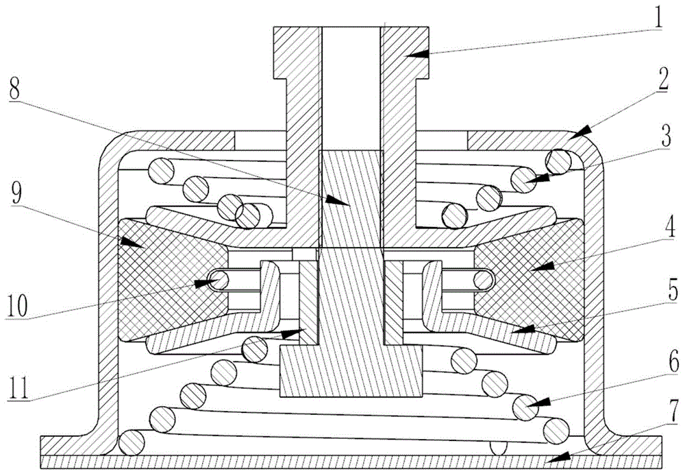
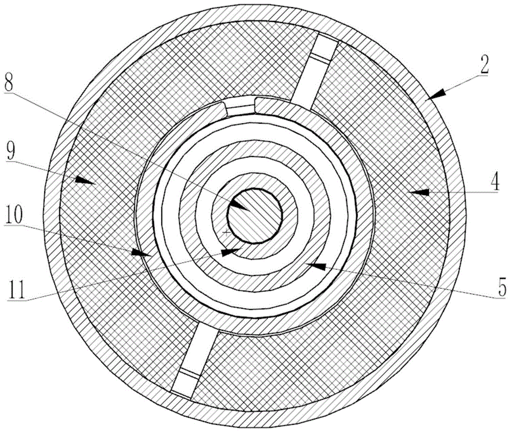
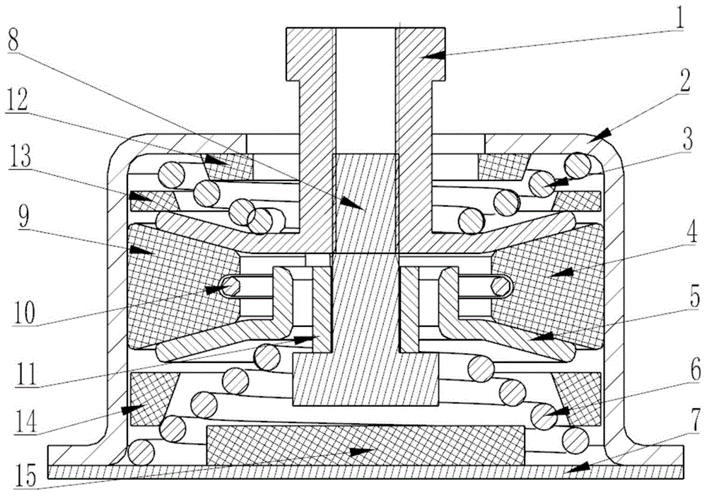
[0026] see image 3 . This embodiment and figure 1 , figure 2 The difference of the specific embodiment shown is that the axial damping washer 12 is arranged between the lower end of the shaft hole of the housing 2 and the disc pressure upper cone spring 3, and the first diameter at the waist of the disc pressure upper cone spring 3 is added. To the damping taper ring pad 13, the second radial damping taper ring pad 14 located at the waist of the lower cone spring 6 and the lower end cover 7 of the housing, and located in the taper hole of the lower cone spring 6, facing the central axis 8 The damping pad 15 of the bottom shaft end step. Other composition, installation and connection relationship and figure 1 , figure 2 The specific embodiment shown is the same.
specific Embodiment approach 2
[0027] see Figure 4 . This embodiment and figure 1 , figure 2 The difference of the specific embodiment shown is that the friction ring 16 installed between the right friction ring sheet 4, the left friction ring sheet 9 and the lower guide umbrella disc 5 and coaxially assembled on the lower guide umbrella disc 5 cylinder is added, Other composition, installation and connection relationship and figure 1 , figure 2 The specific embodiment shown is the same.
specific Embodiment approach 3
[0028] see Figure 5 . This embodiment and figure 1 , figure 2 The difference of the specific embodiment shown is that the structural form of the lower guide umbrella disc 5 and the central axis 8 is changed, the bushing 11 is removed, and a new one is installed in the step hole of the lower guide umbrella disc 5 and assembled on the central axis 8 steps. Friction ring 16 on the shaft, other composition, installation and connection relationship and figure 1 , figure 2 The specific embodiment shown is the same.
PUM
 Abstract
Description
Claims
Application Information
 - R&D
- Intellectual Property
- Life Sciences
- Materials
- Tech Scout
- Unparalleled Data Quality
- Higher Quality Content
- 60% Fewer Hallucinations
Browse by: Latest US Patents, China's latest patents, Technical Efficacy Thesaurus, Application Domain, Technology Topic, Popular Technical Reports.
© 2025 PatSnap. All rights reserved.Legal|Privacy policy|Modern Slavery Act Transparency Statement|Sitemap|About US| Contact US: help@patsnap.com


