
Oil and gas fired boiler having annular combustion chamber

A gas-fired boiler and combustion chamber technology, applied in the field of boilers, to achieve the effect of large variable range, widely popularized and used, and uniform thermal stress

Active Publication Date: 2015-09-23
孔令斌
View PDF6 Cites 4 Cited by
  • Summary
  • Abstract
  • Description
  • Claims
  • Application Information

AI Technical Summary

Problems solved by technology

It can be said that there is no real fuel gas boiler!

Method used


Image

  • Oil and gas fired boiler having annular combustion chamber
  • Oil and gas fired boiler having annular combustion chamber
  • Oil and gas fired boiler having annular combustion chamber

Examples


Embodiment 1

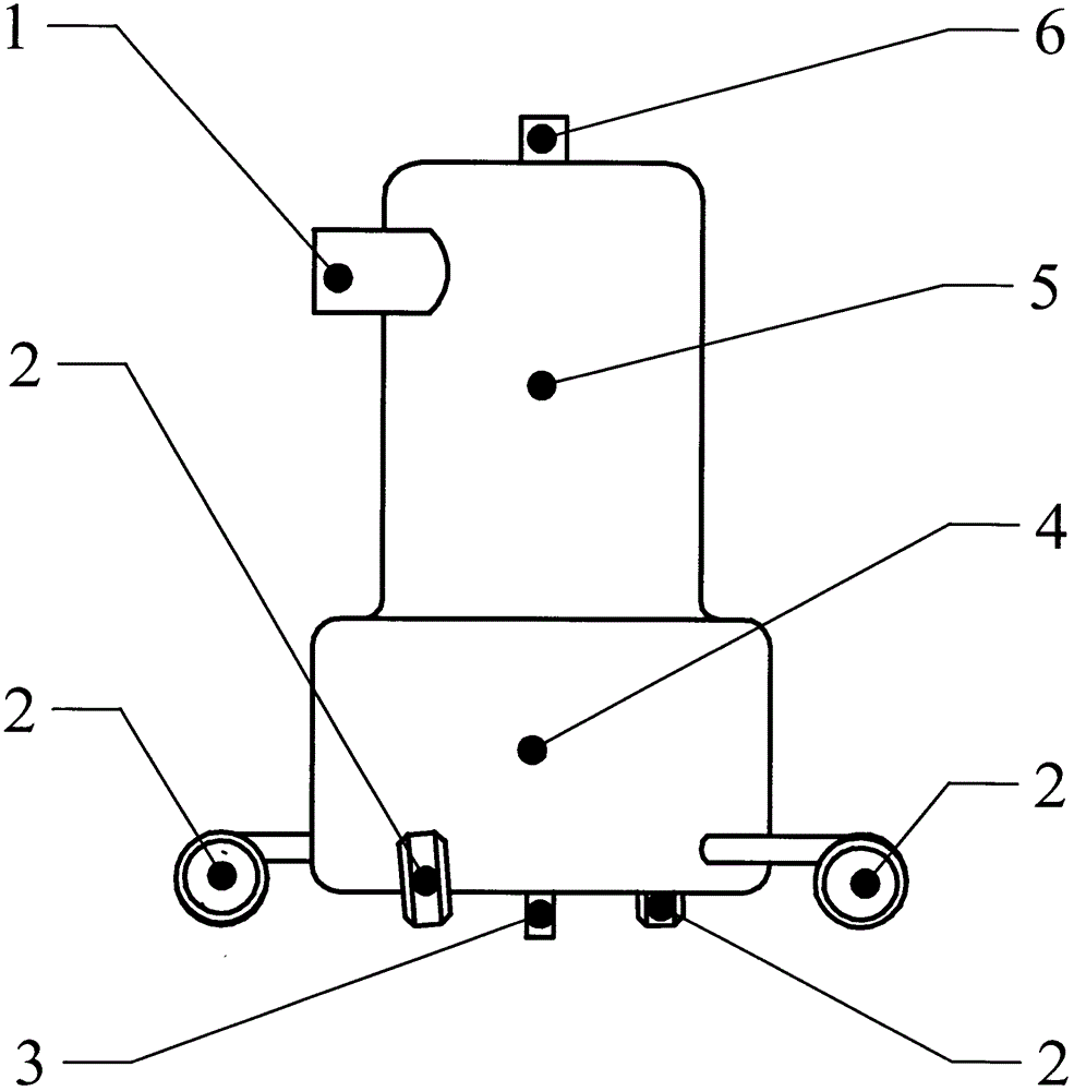
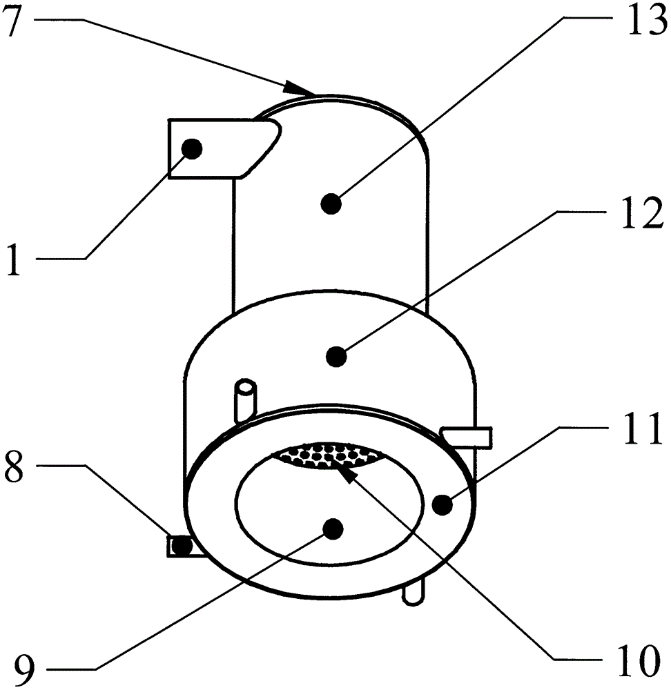
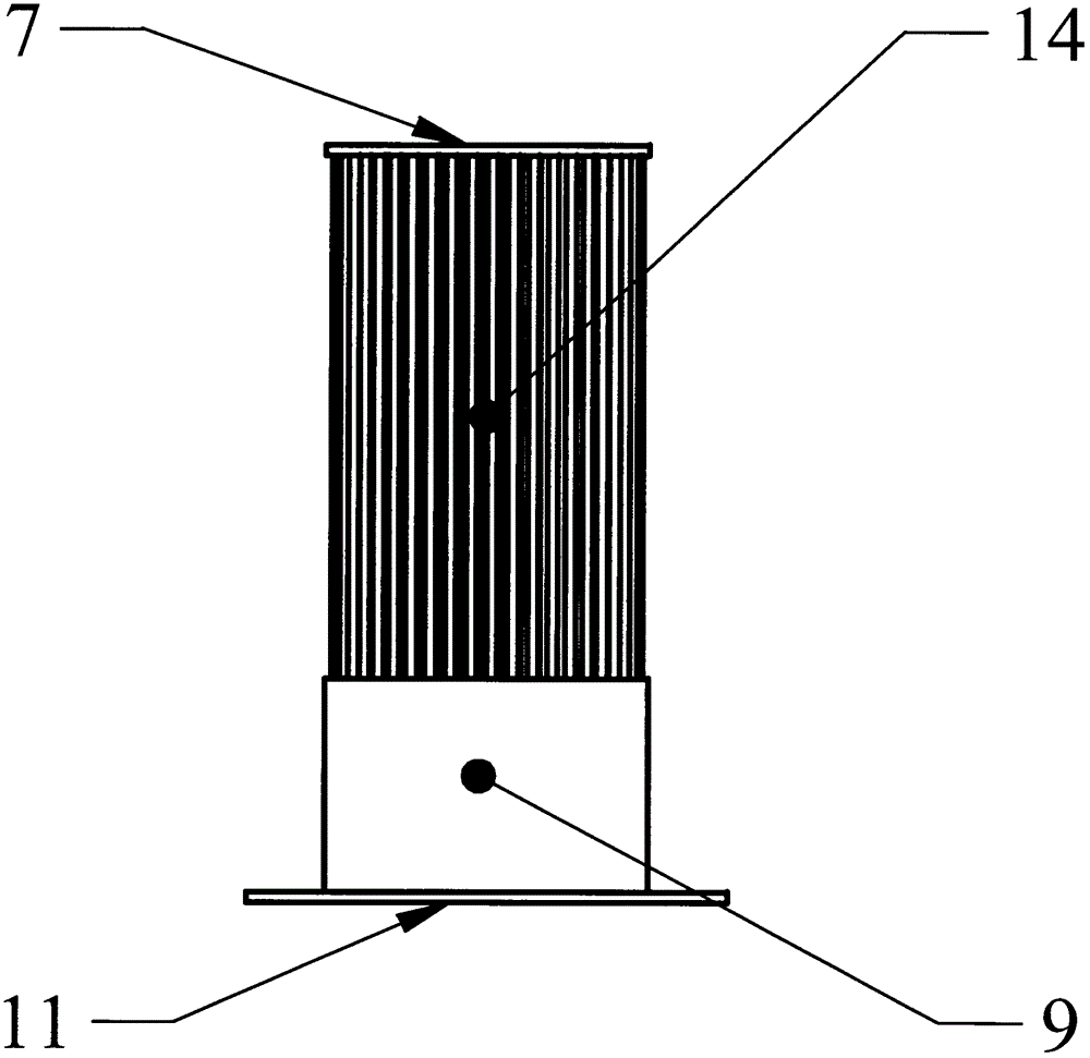
[0017] Embodiment 1: The structure of the fuel-fired gas-fired steam boiler in the annular combustion chamber is as follows figure 1 as shown, figure 2 is the furnace structure diagram, image 3 It is the internal structure diagram of its furnace. The pot shell is arranged upright, four burners 2 are arranged in the same direction along the tangent line of the furnace outside the pot shell, and the furnace is placed in the center of the pot shell. The upper cylinder 5 of the pot shell has an outlet that communicates with the outside of the pot shell and the flue gas discharge pipe 1 in the furnace. There are 4 inlets of pipelines 8 communicating with the outside of the pot shell and the combustion chamber in the furnace gall on the bottom cylinder 4 of the pot shell. The flame injection pipe of the burner 2 is inserted into the combustion chamber through the pipeline 8 connecting the outside of the pot shell and the combustion chamber in the furnace. The pipe 8 connecting...

Embodiment 2

[0019] Example 2: The structure of the fuel-fired gas hot water boiler in the annular combustion chamber is as follows Figure 4 As shown, only one burner is configured due to the small heating power. The water inlet pipe 16 of the hot water boiler is arranged on the top of the pot shell, the water outlet pipe is arranged on the annular combustion chamber, the water outlet pipe leads into the annular hot water tank 15 outside the upper cylinder of the pot shell, and a hot water valve is installed on the hot water tank 15 .

[0020] The working process of embodiment 2 is: the hot water boiler water inlet pipe 16 connects the running water pipe and connects the running water, and the burner ignites and burns. Water temperature just can open the hot water valve on the hot water tank 15 and get hot water when water temperature reaches prescribed temperature. The tap water pipe automatically replenishes water.


PUM


Abstract

The present invention provides an oil and gas fired boiler having an annular combustion chamber. The oil and gas fired boiler is provided with a shell, a furnace and water pipes. A plurality of combustion engines are configured at the periphery of the shell, and the furnace is arranged in the center of the shell. The annular combustion chamber is positioned at a lower portion in the furnace, and the water pipes are positioned at an upper portion in the furnace. The annular combustion chamber is communicated with the upper portion in the furnace to form a smoke flow channel for combustion heat exchange. A space between the furnace and the shell and spaces inside the water pipes form water evaporation upstream channels. The boiler is compact in integral structure, simple in geometrical shape, small in size and high in strength, heat exchange is convenient and sufficient, and thermal stress of the furnace is uniform. The advantage that no solid waste residue is discharged from an oil and gas fired boiler is fully performed, and requirements on fast assembly, modularization and integral assembly of a middle-large sized oil and gas fired boiler can be substantially satisfied. The history that an oil and gas fired boiler uses a structure of a coal fired boiler will be ended. The oil and gas fired boiler having the annular combustion chamber is a boiler according with oil and gas fired characteristics.

Description

Technical field [0001] The invention relates to a boiler, in particular to a fuel gas boiler with an annular combustion chamber. Background technique [0002] China is a big importer of energy, especially the import and consumption of natural gas will experience rapid growth. Many coal-fired boilers cause serious environmental pollution, which also prompts China to develop coal liquefaction and gasification to realize the clean utilization of coal. Therefore, fuel gas boiler technology is the key to realize this transformation of energy consumption structure. [0003] At present, most of the widely used oil-fired gas boilers are small and medium-sized shell-type fire-tube boilers. Shell-type fire-tube boilers cannot meet the requirements of medium and large oil-fired gas-fired boilers. The industry generally believes that the development direction of medium and large fuel gas boilers is water tube boilers. Although there are still a small number of water-tube oil-fired g...

Claims


Application Information

Patent Timeline
Patent Type & Authority Applications(China)
IPC IPC(8): F24H1/08
Inventor 孔令斌
Owner 孔令斌
Learn More