Optical power measuring device

A measurement device and optical power technology, applied in transmission monitoring/testing/fault measurement systems, etc., to achieve the effect of easy use and high integration

Inactive Publication Date: 2015-09-23
SHANGHAI GRANDWAY TELECOM TECH
View PDF3 Cites 7 Cited by
  • Summary
  • Abstract
  • Description
  • Claims
  • Application Information

AI Technical Summary

Problems solved by technology

[0005] The technical problem to be solved by the present invention is that the existing optical power measurement device can only measure the optical power of a single channel, and the defect that multiple connections are required when measuring the ribbon fiber is provided. An optical power measurement device capable of realizing multi-channel measurement is provided

Method used


Image

  • Optical power measuring device
  • Optical power measuring device

Examples


Embodiment 1

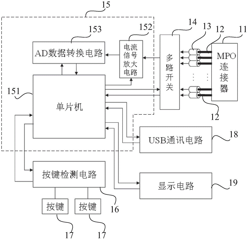
[0032] A kind of optical power measuring device, is used for measuring the power of the multi-path laser signal that transmits in a tested ribbon fiber, see figure 1 , the optical power measurement device includes:

[0033] An MPO connector 11 is used to realize the detachable (movable) connection between the optical fiber and the optical fiber. It precisely butts the two end faces of the optical fiber so that the optical energy output by the transmitting optical fiber can be coupled into the receiving optical fiber to the maximum extent. Go, and minimize the impact on the system due to its intervention in the optical link;

[0034] A ribbon optical fiber 12 with the same number of cores as the number of channels of the MPO connector 11;

[0035] The number of first detectors 13 is the same as the number of channels of the MPO connector 11, the first detector can be an indium gallium arsenide photodetector (InGaAs), the effective detection diameter is 75 μm (micrometer), and ...

Embodiment 2

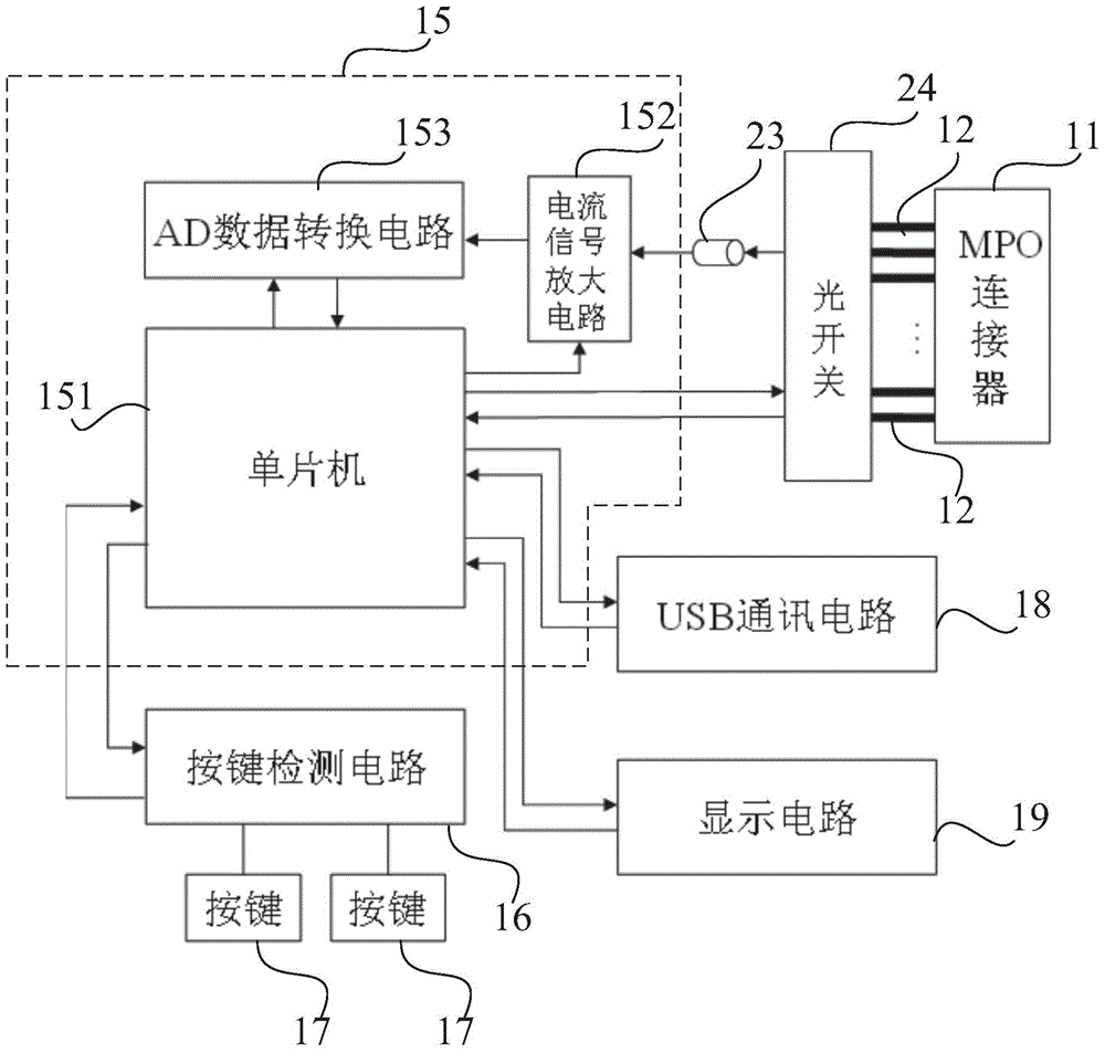
[0045] This embodiment is basically the same as Embodiment 1, the difference is that, see figure 2 , the optical power measuring device of the present embodiment does not include the first detector 13 and the multi-way switch 14 whose number is the same as the number of channels of the MPO connector 11, but includes:

[0046] A second detector 23 and an optical switch 24 (such as a MEMS optical switch) for converting laser signals into current signals; the ribbon fiber 12 is synchronously connected to each channel of the MPO connector 11 and the optical switch 24 for each of the inputs. The output end of the optical switch 24 is electrically connected to the current signal amplifying circuit 152 through the second detector 23 , and the single-chip microcomputer 151 is used to control the optical switch 24 to output a laser signal.

[0047] When using the optical power measuring device to measure the multiple laser signals transmitted in the tested ribbon fiber, it is necessa...


PUM


Abstract

The invention discloses an optical power measuring device. The optical power measuring device comprises a measuring unit provided with a single-chip microcomputer. According to the scheme I, the optical power measuring device further comprises an MPO connector, first detectors whose number is identical with the number of channels of the MPO connector, and a multi-path switch. An output end of the multi-path switch is electrically connected with the measuring unit. The single-chip microcomputer is used for controlling the multi-path switch to output a current signal. Multi-path laser signals of a detected band-shaped optical fiber are respectively transmitted to the first detector through the plurality of channels of the MPO connector. The first detector converts the received laser signals into current signals and further transmits the current signals to a plurality of input ends of the multi-path switch. The current signals output by the multi-path switch are transmitted to the measuring unit. The optical power measuring device overcomes the shortage that an existing optical power meter can only carry out single-channel measurement, and has the advantage that the multi-channel measurement can be carried out conveniently and rapidly.

Description

technical field [0001] The invention relates to an optical power measuring device, in particular to a portable optical power measuring device. Background technique [0002] Because optical fiber has the characteristics of wide frequency band, low loss, light weight, strong anti-interference ability, high fidelity, reliable working performance and low cost, it has gradually replaced traditional information transmission methods in many fields such as communication and data transmission. Optical fiber communication becomes the data transmission solution of choice today. [0003] Although the large-capacity, high-speed, and long-distance information transmission capabilities provided by optical fiber communication have enabled people to obtain a lot of convenience in information transmission and acquisition, people's requirements for data transmission speed, transmission volume and equipment space are constantly increasing. Therefore, a more highly integrated MPO (Multi-fiber P...

Claims


Application Information

Patent Timeline
Patent Type & Authority Applications(China)
IPC IPC(8): H04B10/07
Inventor 汪亮李绍振刘彦阳
Owner SHANGHAI GRANDWAY TELECOM TECH
Why Eureka
Try Eureka