Hollow electrode medium blocking structure

A dielectric barrier, hollow electrode technology, applied in electrical components, plasma and other directions, can solve the problem of increased difficulty in exciting air, and achieve the effects of easy portability, low cost and easy maintenance

Active Publication Date: 2015-09-23
北京三十四科技有限公司
View PDF8 Cites 13 Cited by
  • Summary
  • Abstract
  • Description
  • Claims
  • Application Information

AI Technical Summary

Problems solved by technology

However, both nitrogen and oxygen are diatomic molecules, and the rotational energy level and vibrational energy level are smaller than the electronic energy level. At the same time, oxygen molecules have a strong electronegativity, therefore, the difficulty of exciting the air is greatly increased

Method used


Image

  • Hollow electrode medium blocking structure
  • Hollow electrode medium blocking structure
  • Hollow electrode medium blocking structure

Examples


Embodiment 1

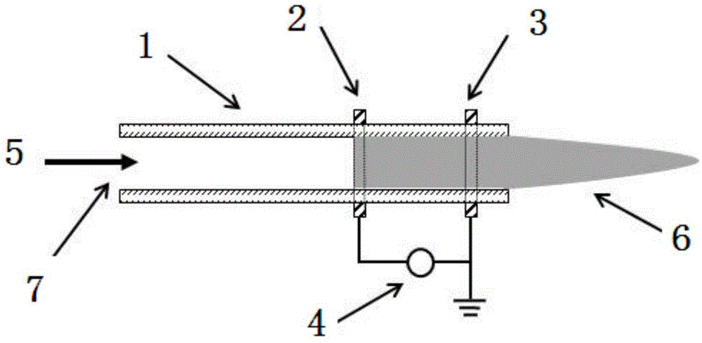
[0036] Embodiment 1: The section length of the air outlet 17 is adjusted to be 1 / 3, 2 / 3 and 1 time of the air inlet 15 respectively, the working gas 18 is air, and the air flows in at a flow rate of 300 L / h through the adjustment of the gas control switch 16 Hollow discharge structure, the frequency 20kHz power supply 13 constantly raises the voltage to excite the hollow discharge structure.

[0037] Such as Figure 6 As shown, the result of the electron density of Example 1 of the present invention increases with the reduction of the gas outlet 17, and the electron density is as high as 10 15 / cm 3 Magnitude.

[0038] Such as Figure 7 As shown, the gas pressure and turbulence distribution results in Embodiment 1 of the present invention decrease with the reduction of the gas outlet 17 (as Figure 7 (a)~ Figure 7 As shown in (c), the internal pressure of the hollow electrode dielectric barrier structure increases, and there is obvious turbulence.

Embodiment 2

[0039] Embodiment 2: The working gas 18 is air, and the air flow rate is controlled by the gas control switch 16 to flow into the hollow discharge structure at 200L / h, 300L / h and 400L / h respectively, and the cross-sectional length of the air outlet 17 is 1 of the air inlet 15. / 3, the high voltage power supply 13 with a frequency of 20kHz continuously raises the voltage to excite the hollow discharge structure.

[0040] Such as Figure 8 As shown, the result of the electron density in Example 2 of the present invention increases with the increase of the air flow velocity, and the electron density is continuously increased, and the electron density is as high as 10 15 / cm 3 Magnitude.

[0041] Such as Figure 9 As shown, the gas pressure and turbulence distribution results increase with the increase of the air flow velocity in the second embodiment of the present invention (as Figure 9 (a)~ Figure 9 As shown in (c), the internal pressure of the hollow electrode dielectri...


PUM


Abstract

The invention relates to a hollow electrode medium blocking structure, comprising a cavity, wherein a high voltage electrode is arranged on the top of the cavity; the bottom of the cavity is provided with a grounding electrode; one end of the high voltage electrode and one end of the grounding electrode are connected to a power supply to constitute a hollow discharge structure; an air inlet is positioned on the high voltage electrode and working gas goes into the hollow discharge structure through the air inlet; the air inlet is provided with a gas regulation and control switch which is controlled by a current control device; an air outlet is positioned on the grounding electrode, and the power supply acts on plasma jet which is generated on the high voltage electrode and injected out from the air outlet. The hollow electrode medium blocking structure has a strong recoil effect, can effectively motivate air and the electron density reaches up to an order of magnitude 1015 / cm3. Besides, the blocking structure motivates the formed plasma jet temperature to reach the indoor temperature, and thus the human body can be touched without being electrically shocked, and the surrounding of the hollow discharge structure barely has the ozone. The hollow electrode medium blocking structure is widely applicable to the nano-material, the biomedicine, environment engineering and more fields.

Description

technical field [0001] The invention relates to a gas discharge structure, in particular to a hollow electrode dielectric barrier structure for forming air plasma jets. Background technique [0002] Plasma is the fourth state of matter and usually consists of positive ions, neutral particles and electrons. Generally, plasma can be divided into high-temperature plasma and low-temperature plasma according to temperature, and low-temperature plasma can be further divided into hot plasma and cold plasma. The temperature of all particles in hot plasma is the same, while the temperature of electrons in cold plasma is as high as tens of thousands of degrees, while the temperature of ions and neutral particles is much lower than that of electrons, so the overall temperature is relatively low. There are abundant active groups in cold plasma, which can be widely used in the fields of surface modification of materials, preparation of nanomaterials, biomedical applications, and environ...

Claims


Application Information

Patent Timeline
Patent Type & Authority Applications(China)
IPC IPC(8): H05H1/26
Inventor 于双王凯乐张珏方竞
Owner 北京三十四科技有限公司
Why Eureka
Try Eureka