Transmission system device of light unmanned helicopter

A technology of unmanned helicopters and transmission systems, applied in the field of light unmanned helicopters, can solve the problems of carrying capacity, low efficiency, difficulty in ensuring assembly accuracy, difficulty in designing lubrication systems, etc., and achieve improved system reliability and easy assembly accuracy , the effect of compact structure

Active Publication Date: 2015-09-30
HEFEI UNIV OF TECH
View PDF7 Cites 6 Cited by
  • Summary
  • Abstract
  • Description
  • Claims
  • Application Information

AI Technical Summary

Problems solved by technology

[0005] At present, the main structure of the main reducer of light unmanned helicopters has the following two types: 1. The main reducer composed of multi-stage gear transmission, including spur gears or helical gears, and bevel gears, so the main reducer box often needs at least Composed of three boxes, it is characterized by simple structure, but the load capacity and efficiency are low, and the range of transmission ratio is small. The lubrication system brought by multiple boxes is difficult to design and the assembly accuracy is also difficult to guarantee; 2. Imitation of military helicopter main The structure of the reducer is composed of one-stage or multi-stage planetary gear train and multi-stage spur or helical gear and transmission. It is arranged longitudinally and has a large longitudinal installation space. The reliability is limited by the life of the planetary gear train bearing. For multi-stage planetary gear train , poor reliability, inconvenient maintenance

Method used


Image

  • Transmission system device of light unmanned helicopter
  • Transmission system device of light unmanned helicopter
  • Transmission system device of light unmanned helicopter

Examples


Embodiment Construction

[0034] The present invention will be further described through the embodiments below in conjunction with the accompanying drawings.

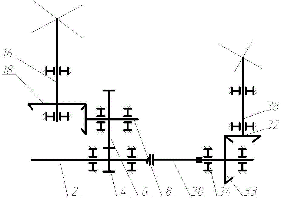
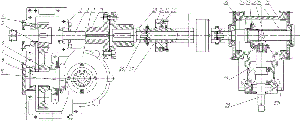
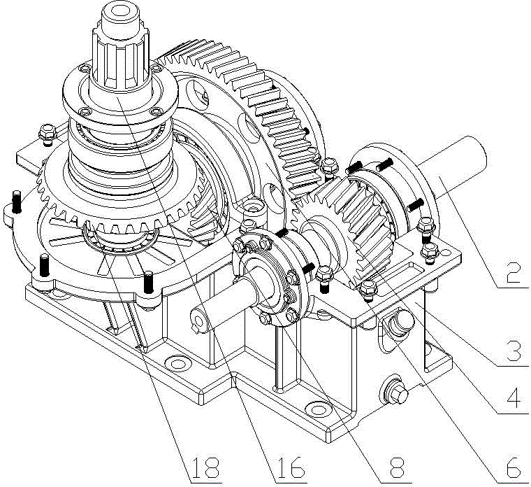
[0035] see figure 1 A transmission system device for a light unmanned helicopter includes a main speed reducer, a tail speed reducer and an intermediate transmission shaft system. see figure 2 , the main reducer includes a high-speed shaft 2, an intermediate shaft 8 and a rotor shaft 16, the high-speed shaft 2 and the intermediate shaft 8 are parallel to each other, and a pair of high-speed gears are meshed between the two; the intermediate shaft 8 and the rotor shaft 16 are perpendicular to each other, and the two The two are driven through a pair of low-speed bevel gears. The tail speed reducer includes a tail reduction input shaft 34 and a tail rotor shaft 38. The tail reduction input shaft 34 and the tail rotor shaft 38 are perpendicular to each other, and the two are driven through a pair of bevel gears. The high-speed shaft 2 and the t...


PUM


Abstract

The invention relates to a transmission system of a light unmanned helicopter. The transmission system comprises a main speed reducer, a tail speed reducer and a middle transmission shaft system, wherein the main speed reducer comprises a high-speed shaft, an intermediate shaft and a rotor shaft; the high-speed shaft and the intermediate shaft are parallel with each other and are in meshed transmission through a pair of high-speed gears; the intermediate shaft and the rotor shaft are perpendicular to each other and are in meshed transmission through a pair of low-speed bevel gears; the tail speed reducer comprises a tail reducing input shaft and a tail rotor shaft which are perpendicular to each other and are in meshed transmission through a pair of bevel gears; the high-speed shaft and the tail reducing input shaft are connected through an intermediate transmission shaft system; the intermediate transmission shaft system comprises a coupling and a pipe shaft; the main speed reducer realizes power transfer and distribution, transfers the low speed to the rotor shaft through the pair of low-speed bevel gears and transfers the high speed to the tail rotor shaft through the intermediate transmission shaft system. The transmission system is simple and reasonable in structural design and convenient to mount and maintain and has the certain significance in design and improvement of transmission systems of military light unmanned helicopters.

Description

technical field [0001] The invention belongs to the technical field of light unmanned helicopters, in particular to a transmission system of light unmanned helicopters. Background technique [0002] Unmanned helicopter refers to an unmanned aircraft that can take off and land vertically by radio ground remote control and autonomous control. It belongs to rotor aircraft in structural form and vertical take-off and landing aircraft in function. In the past ten years, with the research progress of composite materials, power systems, sensors, especially flight control and other technologies, unmanned helicopters have developed rapidly and are increasingly becoming the focus of attention. [0003] To study unmanned helicopters, the design and research of the transmission system cannot be avoided. It is the three key moving parts of the helicopter together with the rotor system and the engine. The function of the transmission system of the unmanned helicopter is to transmit the ...

Claims


Application Information

Patent Timeline
Patent Type & Authority Applications(China)
IPC IPC(8): B64D35/00
Inventor 黄康巩淼周志红
Owner HEFEI UNIV OF TECH
Why Eureka
Try Eureka