Calibration method and system for yaw angles of wind generating set
A technology of a wind power generating set and a calibration method, which is applied in the direction of wind power generators, control of wind power motors, and wind power generation, and can solve problems such as inconsistent torsion angles, reduced service life of power cables of power sets, and long maintenance time of power sets, so as to reduce downtime and maintenance Time, life-prolonging effect
- Summary
- Abstract
- Description
- Claims
- Application Information
AI Technical Summary
Problems solved by technology
Method used
Image

Examples
Embodiment 1
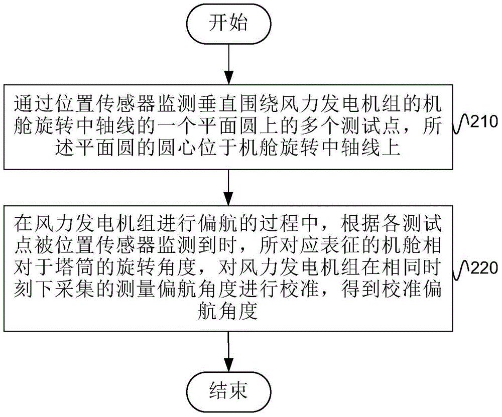
[0031] figure 2 It is a method flowchart of an embodiment of the method for calibrating the yaw angle of the wind power generating set provided by the present invention. Calibration device (the executive body will be referred to as "system" for short in the present invention).
[0032] It is explained here that the state when the unit is not yawing referred to in the present invention is that the unit is shut down, the yaw angle is 0°, and the power cable in the yaw bearing has no torsion. The state where the above three conditions cannot be satisfied at the same time is called the yaw state of the unit (even in the shutdown state, if the yaw angle is not 0, or the power cable in the yaw bearing is twisted, it will be safe for the power cable of the unit. cause an impact, so in this embodiment, it is also considered as the yaw state).
[0033] Such as figure 2 As shown, the wind turbine yaw angle calibration method includes:
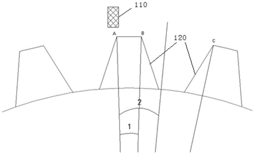
[0034] S210, monitor a plurality of test poi...
Embodiment 2
[0045] Figure 5 The method flowchart of another embodiment of the wind turbine yaw angle calibration method provided by the present invention can be regarded as figure 2 A specific implementation of the illustrated embodiment. Such as Figure 5 As shown, the wind turbine yaw angle calibration method includes the following steps:
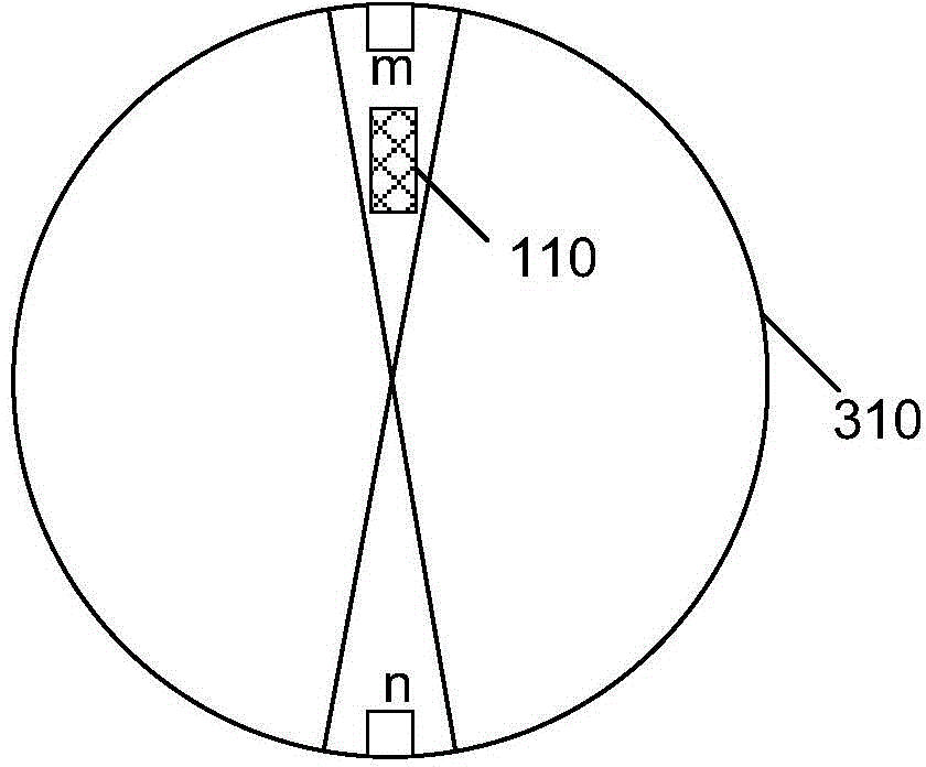
[0046] S510, using a position sensor to monitor a plurality of test points on a plane circle vertically surrounding the central axis of rotation of the nacelle of the wind power generating set, the center of the plane circle being located on the central axis of rotation of the nacelle; The tower of the wind turbine is relatively stationary, and the position sensor is relatively stationary to the nacelle of the wind turbine, or the multiple test points are relatively stationary to the nacelle of the wind turbine, and the position sensor is relatively stationary to the tower of the wind turbine. The content of step S510 is similar to that of the a...
Embodiment 3
[0083] Figure 6 A schematic structural diagram of an embodiment of a wind turbine yaw angle calibration system provided by the present invention, which can be used to perform figure 2 The method steps of the shown embodiment, as Figure 6 As shown, the wind turbine yaw angle calibration system includes: a monitoring module 610 and a calibration module 620 .
[0084] The monitoring module 610 is used to monitor a plurality of test points on a plane circle vertically surrounding the central axis of rotation of the nacelle of the wind power generating set through position sensors, and the center of the circle of the plane is located on the central axis of rotation of the nacelle; wherein, the plurality of test points and The tower of the wind turbine is relatively stationary, and the position sensor is relatively stationary to the nacelle of the wind turbine, or multiple test points are relatively stationary to the nacelle of the wind turbine, and the position sensor is relati...
PUM
 Abstract
Description
Claims
Application Information
 - R&D
- Intellectual Property
- Life Sciences
- Materials
- Tech Scout
- Unparalleled Data Quality
- Higher Quality Content
- 60% Fewer Hallucinations
Browse by: Latest US Patents, China's latest patents, Technical Efficacy Thesaurus, Application Domain, Technology Topic, Popular Technical Reports.
© 2025 PatSnap. All rights reserved.Legal|Privacy policy|Modern Slavery Act Transparency Statement|Sitemap|About US| Contact US: help@patsnap.com