Corrosion-resistant pipe valve structure

An anti-corrosion, pipe valve technology, applied in the direction of valve devices, filtration separation, mechanical equipment, etc., can solve the problems of poor combination of valve and valve body, high safety factor, low corrosion resistance, etc., and achieve low overall cost and excellent connection structure Strong performance and strong corrosion resistance

Inactive Publication Date: 2015-09-30
CHENGDU JUZHI IND DESIGN
View PDF8 Cites 0 Cited by
  • Summary
  • Abstract
  • Description
  • Claims
  • Application Information

AI Technical Summary

Problems solved by technology

[0002] Valves are the control components in the fluid delivery system. They have the functions of cut-off, adjustment, flow diversion, reverse flow prevention, pressure stabilization, flow diversion or overflow pressure relief. Valves used in fluid control systems range from the simplest cut-off valve to extremely complex The various valves used in the automatic control system have a wide variety of varieties and specifications, and the valve materials are also various. Some use cast iron valves, some use cast steel valves, and some use stainless steel valves, which are used in chemical industry pipelines. Most of the valves in the country use metal valves. This kind of valve is widely used in the chemical industry because of its strong pressure resistance and high safety factor, but there are also certain defects, such as poor self-regulation and low corrosion resistance. It acts as a limiter, and the combination between the valve and the valve body is poor, which leads to the limitation of use

Method used


Image

  • Corrosion-resistant pipe valve structure

Examples


Embodiment Construction

[0014] The present invention will now be described in further detail in conjunction with the accompanying drawings, which are simplified schematic diagrams, only schematically illustrating the basic structure of the present invention, and therefore only show the configurations related to the present invention.

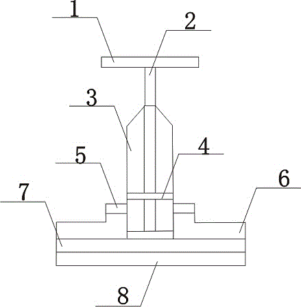
[0015] Such as figure 1 The preferred embodiment of the corrosion-resistant pipe valve structure of the present invention shown includes a valve pipe 1, the bottom of the valve pipe 1 is connected to the valve body 2, the valve body 2 communicates with the valve pipe 1, and the outside of the valve body 2 is covered with a valve plate 3 , the valve plate 3 is fixed on the valve body 2, the valve plate 3 is horizontally provided with a limit plate 4, the limit plate 4 is connected to the valve body 2 by sliding up and down, and a flange 5 is installed on the outside of the valve plate 3, and the flange 5 and The valve plates 3 are integrally connected, the outer surface...


PUM


Abstract

The invention discloses a corrosion-resistant pipe valve structure. The corrosion-resistant pipe valve structure comprises a valve pipe. The bottom of the valve pipe is connected with a valve body. The valve body is communicated with the valve pipe. The outer side of the valve body is covered with a valve plate which is fixed to the valve body. A limiting plate is transversely arranged on the valve plate and connected to the valve body in a vertical sliding mode. A flange is arranged outside the valve plate. The flange and the valve body are integrally connected. An outer wrapping metal pipe is arranged on the lower surface of the flange and connected to the flange in a clamping mode. The lower surface of the outer wrapping metal pipe is connected with a corrosion-resistant plate. The bottom of the valve plate is arranged on the corrosion-resistant plate. The valve body penetrates through a protection plate to be connected with the corrosion-resistant plate. The corrosion-resistant pipe valve structure is high in corrosion resistance, not prone to damage, low in comprehensive chemical production cost, high in connection constitutive property, and capable of playing a good limiting role and avoiding reaction liquid leakage caused by the deflection phenomenon; meanwhile, the corrosion-resistant pipe valve structure has a certain steel constitutive property, and the service life of the corrosion-resistant pipe valve structure is prolonged.

Description

technical field [0001] The invention relates to a pipe valve structure, in particular to a corrosion-resistant pipe valve structure. Background technique [0002] Valves are the control components in the fluid delivery system. They have the functions of cut-off, adjustment, flow diversion, reverse flow prevention, pressure stabilization, flow diversion or overflow pressure relief. Valves used in fluid control systems range from the simplest cut-off valve to extremely complex The various valves used in the automatic control system have a wide variety of varieties and specifications, and the valve materials are also various. Some use cast iron valves, some use cast steel valves, and some use stainless steel valves, which are used in chemical industry pipelines. Most of the valves in the country use metal valves. This kind of valve is widely used in the chemical industry because of its strong pressure resistance and high safety factor, but there are also certain defects, such a...

Claims


Application Information

Patent Timeline
Patent Type & Authority Applications(China)
IPC IPC(8): F16K51/00B01D35/04
CPCF16K51/00B01D35/04
Inventor 文国栋
Owner CHENGDU JUZHI IND DESIGN
Why Eureka
Try Eureka