Optical film, polarizing plate, and method for producing optical film

一种光学膜、偏振片的技术,应用在光学膜领域,能够解决着色等问题,达到着色问题减少、制造工序高效化、对比度高的效果

Inactive Publication Date: 2015-09-30
FUJIFILM CORP
View PDF84 Cites 58 Cited by
  • Summary
  • Abstract
  • Description
  • Claims
  • Application Information

AI Technical Summary

Problems solved by technology

It is difficult to make a retardation film as a retardation film that gives the same effect to light of all wavelengths, which is white light, which is a synthetic wave in which light in the visible light region is mixed. The wavelength plate functions, and it does not function as a 1 / 4 wavelength plate for light of 450nm or 650nm, causing problems such as coloring during use

Method used


Image

  • Optical film, polarizing plate, and method for producing optical film
  • Optical film, polarizing plate, and method for producing optical film
  • Optical film, polarizing plate, and method for producing optical film

Examples


Embodiment 1-1

[0316]

[0317] As the support, a commercially available triacetyl cellulose film "Z-TAC" (manufactured by Fujifilm Corporation) was used. Pass it through a dielectric heating roll support whose temperature is adjusted to 60°C, raise the film surface temperature of the support to 40°C, and then apply a coating amount of 14ml / m on one side of the film using a bar coater 2 An alkali solution having the composition shown below was applied and heated to 110°C. Thereafter, the support was conveyed for 10 seconds under a vapor-type far-infrared heater manufactured by NORITAKE CO., LIMITED. Next, use the same bar coater to coat the surface coated with the alkali solution at 3ml / m 2 Apply pure water. Next, water washing with a jet coater and water removal with an air knife were repeated three times, and then transported in a drying zone at 70°C for 10 seconds and dried to prepare a transparent support treated with alkali saponification. .

[0318]

[0319]

[0320]

[03...

Embodiment 1-2

[0348]

[0349] Alkaline saponification treatment was performed on the surface of the support of the cellulose triacetate film TD80UL (manufactured by Fujifilm). Specifically, the support was immersed in a 1.5N aqueous sodium hydroxide solution at 55°C for 2 minutes, washed in a water bath at room temperature, and neutralized at 30°C with 0.1N sulfuric acid. After washing again in a water bath at room temperature, it was further dried with warm air at 100°C.

[0350] A roll-shaped polyvinyl alcohol film with a thickness of 80 μm was continuously stretched 5 times in the MD direction in an iodine aqueous solution in the same manner as in Example 1-1, and dried to obtain a polarizing film with a thickness of 20 μm.

[0351] By sticking the positive C-plate side of the optical film 1 made above on one side of the above-mentioned polarizing film, and further sticking the above-mentioned cellulose triacetate film through alkali saponification treatment on the other side of the po...

Embodiment 2

[0353]

[0354] The following positive coating liquid 2 for plate A was prepared.

[0355]

[0356] [chem 28]

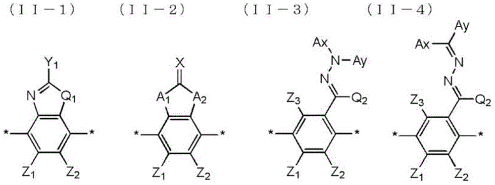
[0357] Reverse wavelength dispersion liquid crystal compound R-2: specific example II-2-2

[0358]

[0359] Cross-linked polymer O-2

[0360]

[0361] However, Tg=10 degreeC of crosslinkable polymer O-2.

[0362]A triacetyl cellulose film having an alignment film 1 on its surface was produced in the same procedure as in Example 1-1, and the alignment film 1 was rubbed. The positive A-plate A-0 forming coating liquid 2 was coated on the friction-treated surface using a bar coater. Next, heat curing was carried out at a film surface temperature of 150°C for 60 seconds, cooled to 70°C, and then irradiated at 1000mJ / cm in the atmosphere using an air-cooled metal halide lamp (manufactured by Eye Graphics Co., Ltd.). 2 The ultraviolet rays fix its orientation state to form a positive A-plate A-0(2). The direction of the slow axis of the formed positive A pl...


PUM

PropertyMeasurementUnit
reflectivityaaaaaaaaaa
glass transition temperatureaaaaaaaaaa
weight-average molecular weightaaaaaaaaaa

Abstract

An optical film of the present invention includes a positive A-plate and a positive C-plate, in which the Re(450), Re(550), and Re(650) of the positive A-plate satisfy the relationship of Re(450)≰Re(550)≰Re(650), the positive A-plate is formed of a cured product of a composition including the liquid crystal compound A, and the positive C-plate is formed of a cured product of a composition including the liquid crystal compound C.

Description

technical field [0001] The present invention relates to an optical film, a polarizing plate and a manufacturing method of the optical film. Background technique [0002] An optical film having a function as a retardation film is often used in a liquid crystal display device. For example, a λ / 4 retardation film is used as a circular polarizing plate in combination with a linear polarizing plate. Various configurations using a combination of a positive A plate and a positive C plate have been proposed as retardation films for high contrast in oblique directions of liquid crystal display devices such as IPS mode (for example, Patent Documents 1 and 2). [0003] On the other hand, Cited Document 3 proposes a retardation film having inverse wavelength dispersion. It is difficult to make a retardation film as a retardation film that gives the same effect to light of all wavelengths, which is white light, which is a synthetic wave in which light in the visible light region is mixe...

Claims


Application Information

Patent Timeline
Patent Type & Authority Applications(China)
IPC IPC(8): G02B5/30G02F1/139G02F1/1335
CPCG02B1/11G02B5/3083C09K19/542G02B5/3016G02B1/12C09K19/3497C09K19/3491C09K19/2007C09K19/2014C09K19/348C09K19/3486C09K19/3494C09K19/601C09K2019/0448C09K2019/3077C09K2019/548
Inventor 高砂理惠松山拓史石黑诚森岛慎一
Owner FUJIFILM CORP
Why Eureka
Try Eureka