Light heating compensating lens and application method thereof

A technology of compensating mirrors and light heating, which is applied in the direction of lasers, laser parts, electrical components, etc., to achieve the effects of convenient operation, simple structure, and good thermal compensation effect

Active Publication Date: 2015-09-30
DALIAN INST OF CHEM PHYSICS CHINESE ACAD OF SCI
View PDF13 Cites 3 Cited by
  • Summary
  • Abstract
  • Description
  • Claims
  • Application Information

AI Technical Summary

Problems solved by technology

This scheme has a good thermal compensation effect, but requires CO2 laser as an additional energy source and complex control equipment

Method used


Image

  • Light heating compensating lens and application method thereof
  • Light heating compensating lens and application method thereof
  • Light heating compensating lens and application method thereof

Examples


Embodiment 1

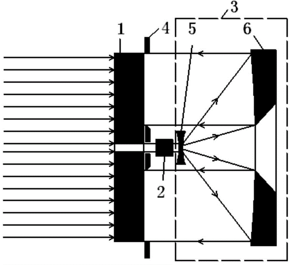
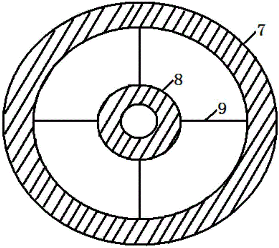
[0035] see figure 1 and figure 2 shown. An optical heating compensation mirror provided by the present invention comprises a mirror body 1, a laser attenuator 2, a laser beam expander system 3 and an aperture 4;

[0036] The center of the mirror body 1 has a through hole for allowing part of the laser light to transmit from the front surface to the rear surface for thermal compensation of the laser cavity mirror;

[0037] Both sides of the mirror body 1 are optically polished, its front surface is coated with a high reflection film, and its rear surface is coated with a high absorption film. The high-reflection film is used to minimize the absorption of laser energy by the mirror body, while the high-absorption film is used to absorb as much laser energy as possible, so as to achieve the best thermal compensation effect with the least energy;

[0038] The laser attenuator 2 is used to attenuate the laser energy transmitted from the front surface to the back surface to an a...

Embodiment 2

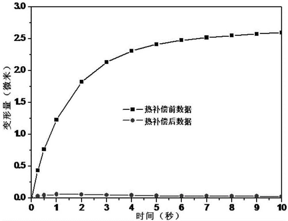
[0046] The following uses a specific calculation example to illustrate the ability of the present invention to efficiently reduce the thermal deformation of the spot part of the laser cavity mirror.

[0047] Using ANSYS software, the thermal compensation effect of single crystal silicon optical heating compensation mirror was simulated and calculated. image 3 The result of the simulation calculation. Among them, the black line is the thermal deformation of the spot part of the laser cavity mirror before thermal compensation, and the red line is the thermal deformation of the spot part of the laser cavity mirror after thermal compensation. It can be seen that during the whole working time, the maximum thermal deformation of the spot part of the laser cavity mirror before thermal compensation is 2.6 microns, while the maximum thermal deformation of the spot part of the laser cavity mirror after thermal compensation is 0.06 microns, which is higher than that before thermal stres...


PUM


Abstract

The invention aims to provide a light heating compensating lens and an application method thereof. The light heating compensating lens includes a lens body, a laser attenuator, a laser beam expanding system and a diaphragm. During a heat compensation process, a part of laser passes through the center of the lens body with a central hole and then the laser attenuator for adjustment of heat compensation energy, the laser beam expanding system composed of a concave lens and a concave mirror for adjustment of diameter of heat compensation light beams, and the diaphragm for adjustment of a heat compensation heating range. The laser then goes to the back face of a mirror coated with a highly absorbing film for heat compensation. According to the invention, light energy of a laser can be utilized for realizing the uniform heat compensation of a laser endoscope and heat deformation of a light spot of the laser endoscope can be reduced to a value which is 1/40 of an original one.

Description

technical field [0001] The invention relates to a light heating compensating mirror and a using method thereof. In particular, it relates to an optical heating compensating mirror which uses the light energy of the laser itself to reduce the thermal deformation of the spot part of the laser cavity mirror to less than 1 / 40 of the original one and its use method. Background technique [0002] With the rapid development of laser technology, the power of lasers is getting higher and higher, and the continuous action time is getting longer and longer. High laser energy causes great thermal deformation of the laser cavity mirror, which significantly reduces the quality of the beam, making it impossible for long-distance transmission, resulting in the failure of the laser system to work normally. Therefore, it is of great significance to reduce the thermal deformation of the laser cavity mirror. [0003] In order to improve the thermal deformation of the laser cavity mirror, many...

Claims


Application Information

Patent Timeline
Patent Type & Authority Applications(China)
IPC IPC(8): H01S3/13
Inventor 石文波张增宝何鑫刘嵚张治国马艳华金玉奇
Owner DALIAN INST OF CHEM PHYSICS CHINESE ACAD OF SCI
Why Eureka
Try Eureka