Screw pump metal stator welding whole-set equipment system

A metal stator and screw pump technology, applied in welding equipment, laser welding equipment, metal processing equipment, etc., can solve the problems of inability to meet technical requirements, inaccurate positioning, large leakage, etc., and achieve uniform and reliable welding rotation speed. The center line is convenient for docking and the effect of reducing thermal deformation

Inactive Publication Date: 2017-11-03
YANCHENG SHIHONG PETROLEUM EQUIP
View PDF3 Cites 2 Cited by
  • Summary
  • Abstract
  • Description
  • Claims
  • Application Information

AI Technical Summary

Problems solved by technology

Although the processing accuracy of the single-section metal stator can meet the technical requirements, the inaccurate positioning and large welding deformation during the welding process of the stator group make the spiral cavity of the whole stator dislocated and discontinuous, and the precision cannot meet the technical requirements. , resulting in low single-stage pressure bearing capacity of the metal stator screw pump, large leakage, and even the matching rotor cannot enter the stator
[0005] So far, other domestic companies that develop all-metal screw pumps generally use the methods of stator connection sleeve positioning connection, concave-convex stator contact surface positioning connection, or positioning pin connection. The cumulative error is large, resulting in a low qualified rate of the metal stator, which cannot meet the design requirements
Moreover, the welding of metal stators generally adopts the argon arc welding process, which has large welding grooves, wide heat-affected zones, large weld thermal stress, and large deformation.
The actual application of thermal recovery wells in oil fields fails due to the bending deformation of the metal stator caused by the thermal stress release of the weld

Method used


Image

  • Screw pump metal stator welding whole-set equipment system
  • Screw pump metal stator welding whole-set equipment system

Examples


Embodiment Construction

[0023] The present invention will be further described in detail below in conjunction with the accompanying drawings and specific embodiments.

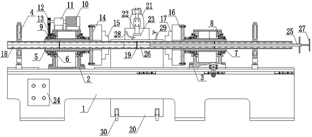
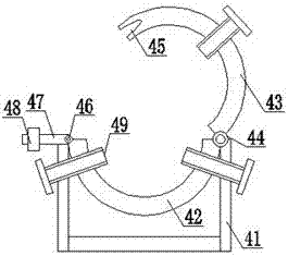
[0024] as attached figure 1The shown metal stator welding complete equipment system of a screw pump according to the present invention includes a processing bed 1, a front support frame 2, a rear support frame 3, a clamping positioning frame 4, a first sleeve 5, and a first bearing 6. The second casing 7, the second bearing 8, the driven pulley 9, the motor 10, the reducer 11, the driving pulley 12, the belt 13, the first rotating disc 14, the first chuck 15, the second rotating disc 16, Second chuck 17, metal stator 18, welding surface 19, welding frame 20, laser welder 21, connecting rod 22, welding head 23, control box 24, stator assembly positioning expansion tire 25, expansion core 26, operating handle 27 , coolant injection pipe 28, lighting lamp 29, roller 30, frame body 41, lower half ring 42, upper half ring 43, first rotati...


PUM

PropertyMeasurementUnit
thermal resistanceaaaaaaaaaa
lengthaaaaaaaaaa

Abstract

The invention relates to a screw pump metal stator welding whole-set equipment system. A front support frame and a rear support frame are separately arranged at the front and the rear of the surface of a machining tool body; clamping positioning racks are symmetrically arranged on two sides of the machining tool body; a first sleeve and a second sleeve are movably mounted in the middles of the front support frame and the rear support frame separately in the transverse direction through a first bearing and a second bearing; a motor is mounted on the top of the front support frame; an output end of the motor is connected with a driving belt pulley through a speed reducer; a first rotating plate and a second rotating plate are separately mounted on opposite side surfaces of the front support frame and the rear support frame; a first chuck and a second chuck are separately arranged on the first rotating plate and the second rotating plate; a welding rack is arranged at a position which is close to the middle of the machining tool body; and a laser welding machine is further mounted on the top of the welding rack. By the technical scheme, the screw pump metal stator welding whole-set equipment system which is accurate in welding and positioning, high in welding speed, high in depth, small in weld joint thermal stress and small in thermal deformation can be provided.

Description

technical field [0001] The invention relates to the field of petroleum machinery, in particular to a metal stator welding complete equipment system of a screw pump. Background technique [0002] As we all know, the current screw pump used in oil production, the stator material is nitrile rubber, heat resistance temperature ≤ 150 ℃, rubber stator and metal rotor interference fit, prone to swelling, wear, aging, damage and other failures in the process of oil production Problems, and because of the interference fit, the operating torque is large, the energy consumption is high, and the service life is low. During the oil extraction process of the screw pump, the sucker rod connected to the rotor accumulates a large amount of torque energy under high torque conditions, which will be released when the pump is shut down for maintenance, causing the sucker rod to reverse at a high speed, which is prone to personal safety accidents. [0003] All major oil fields in my country have...

Claims


Application Information

Patent Timeline
Patent Type & Authority Applications(China)
IPC IPC(8): B23K26/24B23K26/70
CPCB23K26/24B23K26/702
Inventor 徐军
Owner YANCHENG SHIHONG PETROLEUM EQUIP
Why Eureka
Try Eureka