Array photosensitive resistor laser collimation deformation measuring method and apparatus

A photoresistor and laser collimation technology, which is applied to measurement devices, uses optical devices, measures inclination, etc., can solve the problems of high supporting cost of atmospheric laser collimators, many restrictions on measuring point arrangement, and difficulty in automation. Achieve the effect of easy technology upgrade, low cost and wide application range

Inactive Publication Date: 2015-10-07
李跃伟 +1
View PDF4 Cites 20 Cited by
  • Summary
  • Abstract
  • Description
  • Claims
  • Application Information

AI Technical Summary

Problems solved by technology

Atmospheric laser collimation system can observe the horizontal displacement and vertical displacement of the measuring point at the same time, which has the advantages of high precision, high efficiency, good working conditions, and partial automatic observation, but generally speaking, the cost is high and the scope of application is narrow
[0005] However, the atmospheric laser collimation method also has the following four shortcomings: 1) The cost of the atmospheric laser collimator and supporting equipment is high, and the laser is specified in the water conservancy code, and the cost of the laser is high; 2) The distance between the measuring point position and the zone plate The focal length should be matched in advance, and there are many restrictions on the arrangement of measuring points; 3) It is not easy to realize automation; 4) Two reference points (laser point light source and laser detector) need to be buried, and the requirements for visibility are very high, which are mostly used on dams , but it is difficult to apply

Method used


Image

  • Array photosensitive resistor laser collimation deformation measuring method and apparatus
  • Array photosensitive resistor laser collimation deformation measuring method and apparatus
  • Array photosensitive resistor laser collimation deformation measuring method and apparatus

Examples


Embodiment Construction

[0030] The present invention will be further described in detail below in conjunction with the accompanying drawings and embodiments.

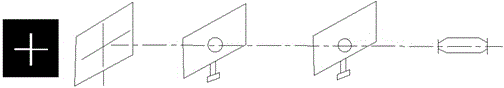
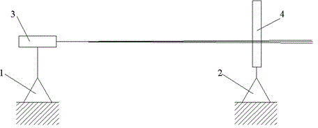
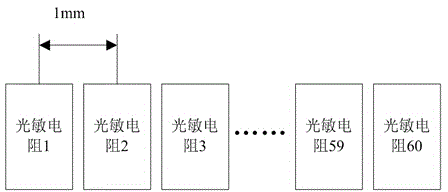
[0031] Such as figure 2 As shown, the present invention first forms a reference line by fixing the reference point 1 (one point) of the station and the laser direction (one line) emitted by the laser module 3 fixed on it, and the array photoresistor fixed on the measuring point 2 of the target object is displaced The array photoresistors with constant spacing in the sensor 4 are equivalent to setting up a standard scale, and jointly form an independent measurement system. Using the sensitivity of photoresistors to light, when the laser is irradiated on the photoresistor before and after, there is a significant difference in the resistance value of the photoresistor, and the voltage value distributed on all the photoresistors of the array is measured and read through the ADC scanning circuit, and then the resistance value is screened out throu...


PUM


Abstract

The invention discloses an array photosensitive resistor laser collimation deformation measuring method and apparatus. The method comprises, first of all, determining a reference point (1) and a measuring point (2), arranging one laser module (3) for emitting a laser towards a fixed direction on the reference point (1), and arranging one array photosensitive resistor displacement sensor (4) on the measuring point (2); emitting the laser towards the measuring point (2) through the laser module (3) to form a stable reference line, wherein the laser leaves a stable light spot on the array photosensitive resistor displacement sensor (4); calculating a laser light spot center point through a laser light spot influence interval; and through scale change of the laser light spot center point on the array photosensitive resistor displacement sensor (4), identifying displacement change of a target object in an array photosensitive resistor direction. The method and apparatus provided by the invention can realize displacement monitoring of an object body relative to the reference line so as to realize multiple monitoring items including horizontal displacement, vertical displacement, inclination, disturbance and the like in the field of deformation monitoring.

Description

technical field [0001] The invention relates to the field of geodetic surveying technology, in particular to a laser alignment measurement method based on an array photoresistor displacement sensor capable of performing an automatic deformation (horizontal, displacement, inclination or disturbance) monitoring on a monitoring object during on-site implementation and its device. Background technique [0002] At present, deformation monitoring projects mostly use the geodetic methods of distance measurement, angle measurement, leveling and collimation, and complete monitoring projects such as vertical displacement, horizontal displacement, inclination and disturbance through the plane control network. It is characterized by using theodolite, level, rangefinder, laser collimator and other instruments to measure the relative distance between the measuring points in the network according to the reference line method (line of sight, laser collimation, vertical line, level line, etc...

Claims


Application Information

Patent Timeline
Patent Type & Authority Applications(China)
IPC IPC(8): G01B11/02G01B11/16G01C9/00
Inventor 李跃伟曹亚萍
Owner 李跃伟
Why Eureka
Try Eureka