
Device and method for removing interface dirt in post-processing extraction equipment

A technology of interface dirt and extraction equipment, which is applied in the direction of reactor fuel elements, nuclear power generation, climate sustainability, etc., can solve the problems of lack of interface dirt removal devices, etc., and achieve the effect of convenient operation, reliable actual operation, and easy mastery

Active Publication Date: 2017-11-21
CHINA INSTITUTE OF ATOMIC ENERGY
View PDF5 Cites 0 Cited by
  • Summary
  • Abstract
  • Description
  • Claims
  • Application Information

AI Technical Summary

Problems solved by technology

[0004] In order to solve the problem of lack of suitable interface dirt removal device in the reprocessing process of nuclear reactor spent fuel, the present invention provides a device and method for removing interface dirt in reprocessing extraction equipment

Method used


Image

  • Device and method for removing interface dirt in post-processing extraction equipment

Examples


Embodiment 1

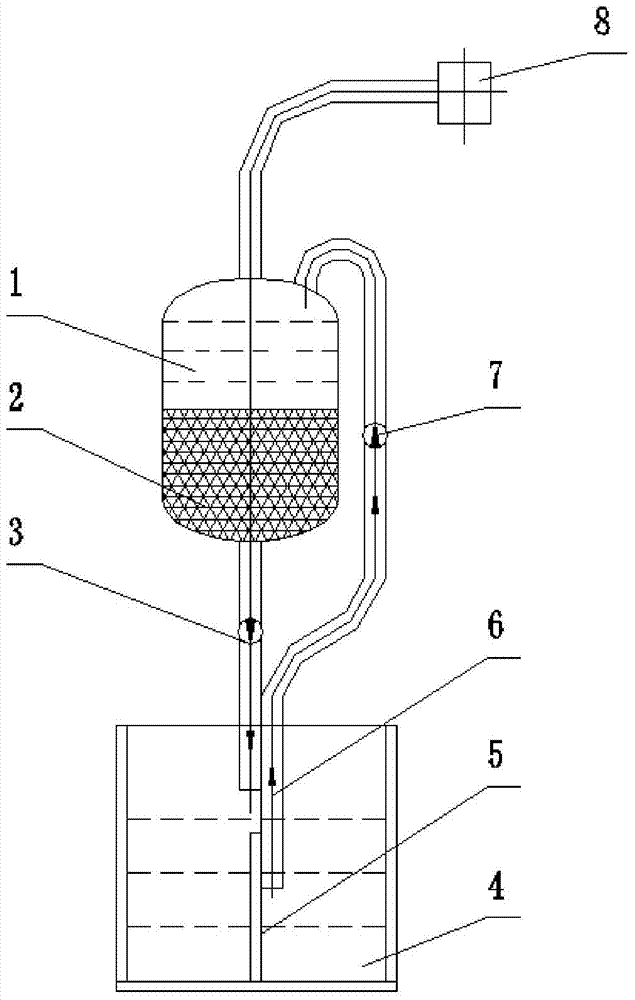
[0015] as attached figure 1 As shown, the removal device of the interface dirt in the post-processing extraction equipment of the present invention includes a liquid storage tank (glass material, volume 10ml), a suction pipe, a liquid discharge pipe, and a pulse generator. The filter material (sintered glass sand of G3) forms a liquid storage space above the interior of the liquid storage tank; one end of the suction pipe communicates with the top of the liquid storage tank, and the other end opens below the liquid storage tank; the drain pipe and the storage tank The bottom of the liquid pool is connected; the suction pipe and the liquid discharge pipe are provided with one-way valves; the top of the liquid storage pool is also connected with the pulse generator through a pipeline.

[0016] A liquid level control pillar can also be arranged at the mouth of the suction pipe; the liquid level control pillar is a pillar fixed together with the pipette and whose length exceeds th...

Embodiment 2

[0018] The interface dirt removal device in the post-processing extraction equipment of Example 1 is used to remove the interface dirt of a certain extraction material liquid, and the specific operations are as follows:

[0019] First, place the nozzle of the suction pipe at the interface dirt in the extraction equipment, and under the drive of the pulse generator, the feed liquid with the interface dirt is sucked into the liquid storage pool through the suction tube, and passes through the filter material in the liquid storage pool. After filtering out the interface dirt, the feed liquid is returned to the extraction equipment through the discharge pipe to realize the removal of the interface dirt. After about 10 minutes of operation, the feed liquid in the extraction equipment gradually clarifies, which proves that the operation effect of the device is good.


PUM


Abstract

The invention relates to matched equipment and method for nuclear reactor spent fuel after-treatment and aims at solving the problem of a lack in an applicable interphase crud removing device in a nuclear reactor spent fuel after-treatment process. The invention provides a device and a method for removing interphase cruds in after-treatment extraction equipment. The device comprises a liquid storage pond, a liquid suction pipe, a liquid drainage pipe and a pulse generator, wherein a filter material is arranged at the internal lower portion of the liquid storage pond; one-way valves are arranged on both the liquid suction pipe and the liquid drainage pipe; the top portion of the liquid storage pond is communicated with the pulse generator through a pipeline. The method comprises the steps of sucking feed liquid containing interphase cruds into the liquid storage pond, filtering the feed liquid and returning the feed liquid into extraction equipment through the liquid drainage pipe to realize the removal of interphase cruds. The removing device provided by the invention has the advantages of simple structure, convenience in installation and operation, easiness in scaling, reliable actual operation and the like; the removing method is convenient to operate and easy to master, and better satisfies the requirement of long-distance operation.

Description

technical field [0001] The invention relates to an auxiliary equipment and method for post-treatment of nuclear reactor spent fuel, in particular to a device and method for removing interface dirt in post-processing extraction equipment. Background technique [0002] In the reprocessing of nuclear reactor spent fuel, some separation processes use solvent extraction methods. Due to the fine solid particles (a few microns in diameter) contained in the extracted aqueous phase feed liquid, and the complex composition of the aqueous phase feed liquid, the combination of some elements (such as Tc, Ru, Zr, Mo, Pu) will form secondary precipitation, Some elements will also form solids with the radiolysis products of the organic phase. When these solid substances enter the extraction equipment (such as mixing and settling tanks, pulse extraction columns), they will form interface dirt at the interface between the organic phase and the aqueous phase. These interface dirt will not flo...

Claims


Application Information

Patent Timeline
Patent Type & Authority Patents(China)
IPC IPC(8): G21C19/50G21F9/12
CPCG21C19/50G21F9/125Y02E30/30
Inventor 何辉常尚文李高亮晏太红郑卫芳
Owner CHINA INSTITUTE OF ATOMIC ENERGY
Learn More