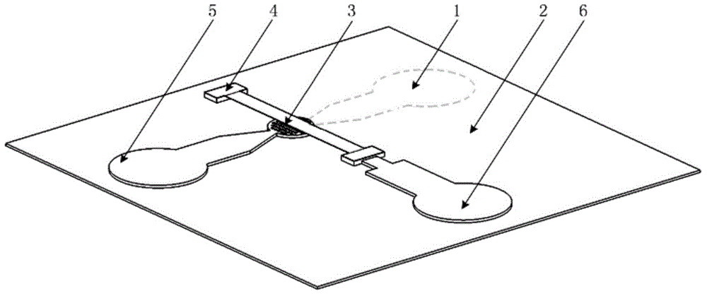
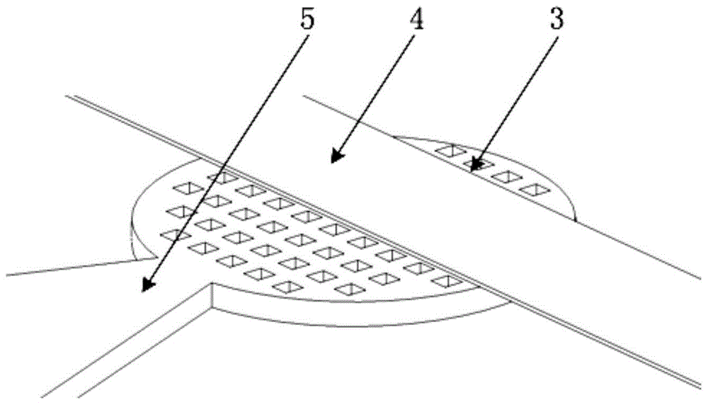
Solid-state insulating dielectric pulse power switch and preparation method thereof
A technology of pulse power switch and insulating medium, which is applied in the manufacture of semiconductor/solid-state devices, electric solid-state devices, electrical components, etc., can solve the problems of complex structure and poor process feasibility of auxiliary gas-solid breakdown, and achieve simple and easy implementation Effect
- Summary
- Abstract
- Description
- Claims
- Application Information
AI Technical Summary
Problems solved by technology
Method used
Image

Examples
Embodiment 1
[0051] The first step is to sputter a Cr / Cu (Cr200nm, Cu800nm) metal layer on a 2mm thick glass substrate;
[0052] In the second step, spin-coat AZ4903 photoresist with a thickness of 20 μm, and photolithographically pattern the micro-electroformed Ni metal layer to prepare the bottom electrode;
[0053] In the third step, acetone is used to release the photoresist sacrificial layer in the second step;
[0054] In the fourth step, the above bottom electrode structure is covered by spin coating with liquid polyimide, and the spin coating thickness is 30 μm;
[0055] The fifth step is to use 60°C (30min heating and 60min insulation), 90°C (20min heating and 90min insulation), 250°C (50min heating and 100min insulation), and the furnace cooling program to dry the above liquid polyimide film, and use Water sandpaper with a particle size of 5 μm is manually polished to expose the bottom electrode to the surface of the polyimide dielectric film;
[0056] Step 6, sputtering a Cr / C...
Embodiment 2
[0062] The first step is to sputter a Cr / Cu (Cr200nm, Cu800nm) metal layer on a 2mm thick glass substrate;
[0063] In the second step, spin-coat AZ4903 photoresist with a thickness of 20 μm, and photolithographically pattern the micro-electroformed Ni metal layer to prepare the bottom electrode;
[0064] In the third step, acetone is used to release the photoresist sacrificial layer in the second step;
[0065] The fourth step is to use liquid water glass inorganic medium to spin-coat the above-mentioned bottom electrode structure, and the spin-coating thickness is 30 μm;
[0066] The fifth step is to use 90°C (50min to heat up and 60min to keep warm), 180°C (50min to heat up to 90min to keep warm), and the above-mentioned liquid water glass inorganic medium film is dried with the program control scheme of furnace cooling, and the water sandpaper with a particle size of 2μm is used for manual polishing , so that the bottom electrode is exposed to the surface of the dielectri...
Embodiment 3
[0073] The first step is to sputter a Cr / Cu (Cr200nm, Cu800nm) metal layer on a 2mm thick glass substrate;
[0074] In the second step, spin-coat AZ4903 photoresist with a thickness of 20 μm, and photolithographically pattern the micro-electroformed Ni metal layer to prepare the bottom electrode;
[0075] In the third step, acetone is used to release the photoresist sacrificial layer in the second step;
[0076] In the fourth step, the above bottom electrode structure is covered by spin coating with liquid polyimide, and the spin coating thickness is 30 μm;
[0077] The fifth step is to use 60°C (30min heating and 60min insulation), 90°C (20min heating and 90min insulation), 250°C (50min heating and 100min insulation), and the furnace cooling program to dry the above liquid polyimide film, and use Water sandpaper with a particle size of 5 μm is manually polished to expose the bottom electrode to the surface of the polyimide dielectric film;
[0078] Step 6, sputtering a Cr / C...
PUM
 Abstract
Description
Claims
Application Information