Axial magnetic gear employing stator permanent magnetism structure at low-speed rotor side

A low-speed rotor, axial magnetic technology, applied in the field of variable-speed transmission, can solve the problems of difficult processing and manufacturing, low mechanical reliability, etc., and achieve the effects of low manufacturing cost, low processing cost, and improved utilization rate

Active Publication Date: 2015-10-07
CHINA UNIV OF PETROLEUM (EAST CHINA)
View PDF4 Cites 10 Cited by
  • Summary
  • Abstract
  • Description
  • Claims
  • Application Information

AI Technical Summary

Problems solved by technology

[0004] Technical problem: In order to solve the problems of low mechanical reliability and difficult manufacturing

Method used


Image

  • Axial magnetic gear employing stator permanent magnetism structure at low-speed rotor side
  • Axial magnetic gear employing stator permanent magnetism structure at low-speed rotor side
  • Axial magnetic gear employing stator permanent magnetism structure at low-speed rotor side

Examples


Embodiment Construction

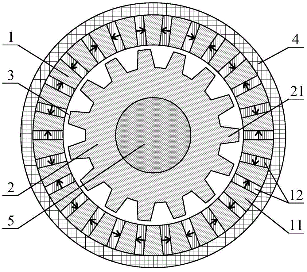
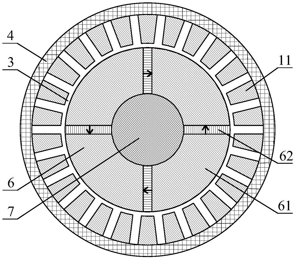
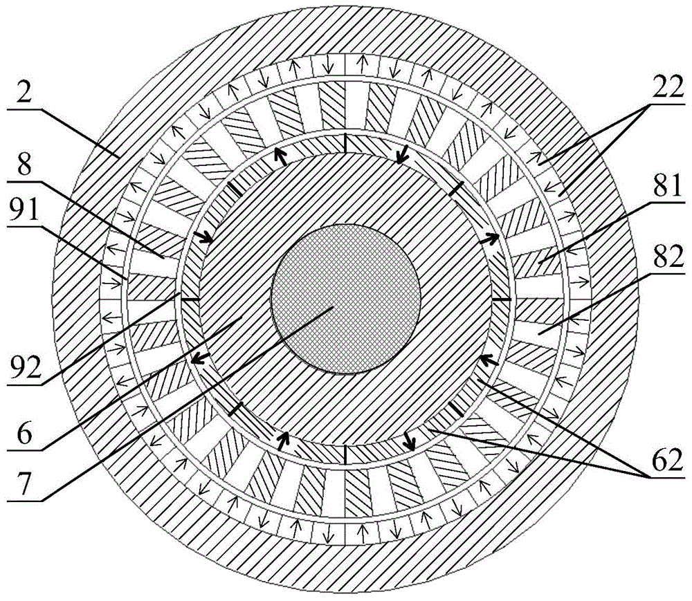
[0020] The axial magnetic gear of the present invention comprises a stator 1, a low-speed rotor 2, a low-speed rotating shaft 5, a high-speed rotor 6, a high-speed rotating shaft 7 and a casing 4; the low-speed rotor 2 is fixedly arranged on the low-speed rotating shaft 5, and the low-speed rotor 2 is an annular guide The magnet has low-speed rotor salient poles 21 arranged equidistantly on its outer ring; the high-speed rotor 6 is fixed on the high-speed rotating shaft 7, and the high-speed rotor 6 is a ring structure, including a high-speed rotor core 61 and a spoke-type embedded high-speed The high-speed rotor permanent magnet 62 of the rotor core 61, the high-speed rotor permanent magnet 62 is magnetized tangentially along the circumference, and the magnetization direction of adjacent permanent magnets is opposite; the low-speed rotor 2 and the high-speed rotor 6 are arranged axially, coaxially There is a gap between them, and the outer diameters of the two are the same; th...


PUM


Abstract

The invention discloses an axial magnetic gear. The axial magnetic gear comprises a low-speed rotor, a high-speed rotor and a stator. The low-speed rotor and the high-speed rotor are arranged coaxially in the axial direction and have the same outer diameter. The low-speed rotor is an annular magnetizer. Evenly spaced low-speed rotor salient poles are arranged on the outer ring of the annular magnetizer. The high-speed rotor comprises a high-speed rotor iron core and a high-speed rotor permanent magnet embedded in the high-speed rotor iron core. The stator has an annular structure composed of evenly-spaced magnetic conductive blocks. The stator is fixed outside the high-speed rotor and the low-speed rotor coaxially. Two end faces of the stator are parallel and level to the outer end faces of the high-speed rotor and the low-speed rotor. A permanent magnet is filled between adjacent stator magnetic conductive blocks corresponding to the low-speed rotor side. Air gaps are arranged between the stator and the high-speed rotor and between the stator and the low-speed rotor. A gap is arranged between the high-speed rotor and the low-speed rotor in the axial direction, and free rotation of the high-speed rotor and the low-speed rotor can be ensured. The axial magnetic gear achieving variable transmission by utilization of the harmonic wave magnetic field coupling effect has characteristics of high mechanical reliability and convenient processing and manufacturing.

Description

technical field [0001] The invention relates to an axial magnetic gear suitable for non-contact variable speed drive, belonging to the technical field of variable speed transmission. Background technique [0002] In industrial applications, many occasions that require variable speed drives are usually realized by mechanical devices such as bulky gearboxes. The use of mechanical gearboxes will inevitably bring about problems such as noise, vibration, friction loss, and regular maintenance, and will significantly increase the size and weight of the transmission system. In addition, mechanical gears do not have overload self-protection capabilities. When the transmitted torque exceeds the bearing capacity of mechanical teeth, safety accidents are prone to occur. [0003] In comparison, the magnetic gear uses magnetic field coupling to transmit torque. It is a non-contact variable speed transmission device that does not have problems such as noise, vibration, friction loss, and...

Claims


Application Information

Patent Timeline
IPC IPC(8): H02K51/00H02K16/02H02K1/24H02K1/27H02K1/17
Inventor 李祥林王玉彬
Owner CHINA UNIV OF PETROLEUM (EAST CHINA)
Why Eureka
Try Eureka