
Cutting fluid recovering device for grinding machine

A recycling device and cutting fluid technology, applied in grinding/polishing equipment, filtration circuits, filtration and separation, etc., can solve the problems of low recovery rate, poor recovery quality, and multiple cutting fluids.

Inactive Publication Date: 2015-10-14
宁波神丰汽车部件有限公司
View PDF9 Cites 16 Cited by
  • Summary
  • Abstract
  • Description
  • Claims
  • Application Information

AI Technical Summary

Problems solved by technology

[0003] The purpose of the present invention is to overcome the disadvantages that the cutting fluid processed by the current cutting fluid processing device still carries more sand particles, the recovery quality is poor, and the separated iron filings remain more cutting fluid, and the recovery rate is low. , to provide a grinding machine cutting fluid recovery device with better quality of cutting fluid recovery and higher recovery rate

Method used


Image

  • Cutting fluid recovering device for grinding machine

Examples


Embodiment Construction

[0014] The present invention will be further described below in conjunction with the accompanying drawings.

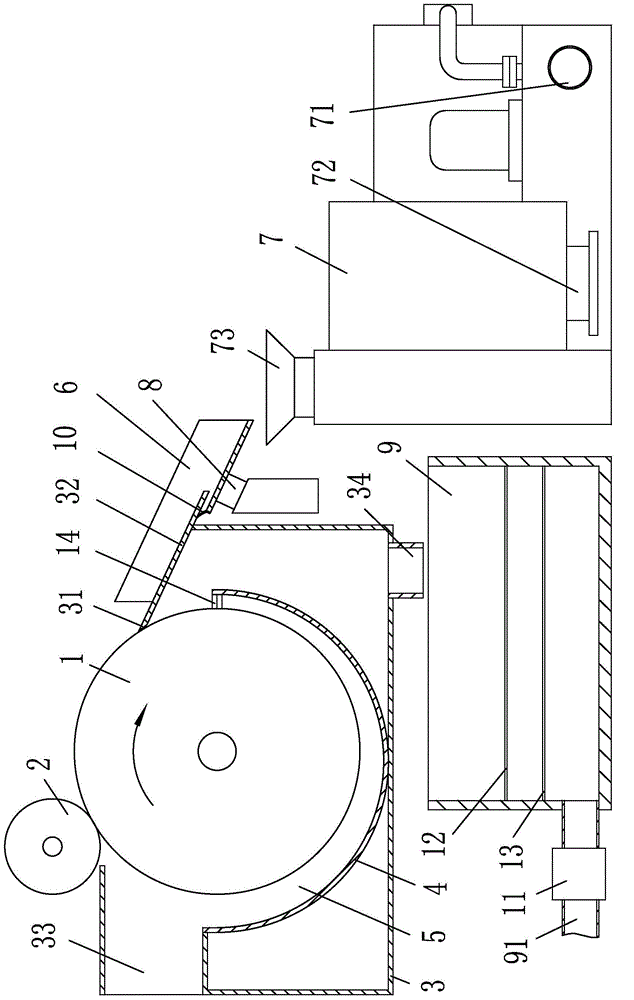
[0015] as attached figure 1 Shown: a grinding machine cutting fluid recovery device, including a housing 3, a magnetic roller 1 and a soft roller 2 pivotally connected to the housing 3 through bearings, located on the lower side of the magnetic roller 1 and welded to the housing 3 at both ends Arc-shaped support plate 4, iron filings cutting fluid separation device, cutting fluid filtering device; housing 3 has a scraping end 31 at the high-end scraping ramp 32, a liquid inlet 33 at the upper rear side of the magnetic drum 1 and a bottom The liquid outlet 34 of the magnetic roller 1 and the arc-shaped supporting plate 4 form a cutting fluid channel 5 with one end connected to the liquid inlet 33; the scraper end 31 is located above the other end of the cutting fluid channel 5; the soft roller 2 is located at the scraper Between the chip end 31 and the liquid inlet 33....


PUM


Abstract

The invention relates to the field of recovery of cooling liquid of machine tools and provides a cutting fluid recovering device for a grinding machine. The cutting fluid recovering device for the grinding machine comprises a shell, a magnetic roller, a soft roller, an arc-shaped supporting plate, a scrap iron cutting fluid separation device and a cutting fluid filtering device, wherein both the magnetic roller and the soft roller are connected with the shell in a pivoted mode; the arc-shaped supporting plate is located under the magnetic roller, and the two ends of the arc-shaped supporting plate are connected with the shell. The shell is provided with an oblique scrap scraping plate, a fluid inlet and a fluid outlet, wherein the scrap scraping end of the oblique scrap scraping plate is located at the high end, the fluid inlet is located in the back side of the upper portion of the magnetic roller, and the fluid outlet is located in the bottom. A cutting fluid channel is formed between the magnetic roller and the arc-shaped supporting plate, and one end of the cutting fluid channel is communicated with the fluid inlet. The scrap scraping end is located above the other end of the cutting fluid channel. The soft roller is located between the scrap scraping end and the fluid inlet. The cutting fluid recovering device for the grinding machine is good in cutting fluid recovering quality and high in cutting fluid recovering rate.

Description

technical field [0001] The invention relates to the field of machine tool coolant recovery, in particular to a grinding machine cutting fluid recovery device. Background technique [0002] After the grinding machine cutting fluid is pumped out by the cooling pump, it is sprayed on the processing surface. After cooling the workpiece, the cutting fluid carrying a large amount of grinding wheel mud and processing iron chips enters the magnetic separation device through the sewage output pipe, and flows through the magnetic separation device. During the process of the rotating magnetic drum, the iron filings in the cutting fluid are sucked out, and the cutting fluid flows back into the water tank, where the dirt is deposited on the sedimentation plate in the water tank and then reused; the cutting fluid treated by the traditional cutting fluid treatment device There are still more sand particles in the liquid, the recovery quality is poor, and there are more cutting fluid in the...

Claims


Application Information

Patent Timeline
Patent Type & Authority Applications(China)
IPC IPC(8): B24B57/00B01D36/00
CPCB01D36/02B03C1/10B24B57/00
Inventor 翁国畅徐文
Owner 宁波神丰汽车部件有限公司
Learn More