Compound feed pump turbine for thermal power plant and thermodynamic system

A technology for feedwater pump steam turbines and thermal power plants, which is applied in the direction of steam engine devices, machines/engines, mechanical equipment, etc., and can solve the problem of affecting the heat recovery cycle efficiency of the unit, the inability to use high-quality energy more reasonably, and the pure condensing machine Low operating efficiency and other issues, to achieve the effect of reducing land occupation, reducing project cost, and simplifying the system

Active Publication Date: 2015-10-14
山西漳电科学技术研究院(有限公司) +2
View PDF6 Cites 9 Cited by
  • Summary
  • Abstract
  • Description
  • Claims
  • Application Information

AI Technical Summary

Problems solved by technology

If the direct air-cooled unit adopts the method that the exhaust steam of the pure condensing unit is directly discharged into the exhaust device of the main engine, it is necessary to further consider the sudden drop of back pressure caused by strong winds in summer, and the design margin of the pure condensing unit needs to be increased. The margins are superimposed layer by layer, resulting in low operating efficiency of the pure condens...

Method used


Image

  • Compound feed pump turbine for thermal power plant and thermodynamic system
  • Compound feed pump turbine for thermal power plant and thermodynamic system
  • Compound feed pump turbine for thermal power plant and thermodynamic system

Examples


Embodiment Construction

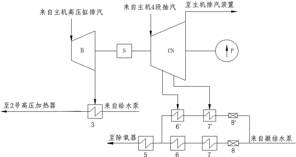
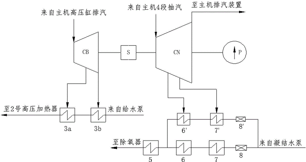
[0022] like figure 2 , image 3 As shown, a composite feedwater pump steam turbine and thermal system used in a thermal power plant, including steam extraction and condensing small steam turbine CN, small condensing machine No. 6' low-pressure heater 6', small condensing machine No. 7' The low-pressure heater 7' and the condensate flow regulating valve 8' of the extraction and condensing small machine, the output end of the steam extraction and condensing small steam turbine CN is connected to the boiler feed water pump P, the low-pressure heater 6' of the small extraction condensing machine 6' and the extraction The low-pressure heater 7' of the small condensing machine 7' is respectively connected to the steam extraction condensing small steam turbine CN through the steam extraction pipeline, and the low-pressure heater 6' of the small condensing machine 6' is connected to the small condensing machine 7 through the condensate pipe. 'No. low-pressure heater 7' and condensat...


PUM


Abstract

The invention relates to a compound feed pump turbine for a terminal power plant and a thermodynamic system, in particular to a feed pump compound turbine driving system used for the thermodynamic power plant. The feed pump compound turbine driving system comprises a steam extracting and condensing type small turbine, an extracting and condensing small machine low-pressure heater 6', an extracting and condensing small machine low-pressure heater 7' and a condensing water flow adjusting valve. The output end of the steam extracting and condensing type small turbine is connected with a boiler feed pump. The extracting and condensing small machine low-pressure heater 6' and the extracting and condensing small machine low-pressure heater 7' are connected with the steam extracting and condensing type small turbine through steam extracting pipelines. The extracting and condensing small machine low-pressure heater 6' is connected with the extracting and condensing small machine low-pressure heater 7' and the condensing water flow adjusting valve in series through a condensed water pipeline, and condensing pipelines formed through series connection are connected to a condensing pipeline which is formed through series connection of a main machine low-pressure heater 6, a main machine low-pressure heater 7 and a main machine condensed water flow adjusting valve in parallel. The problems of a feed pump configuration manner and slightly high energy consumption which trouble a direct air-cooling unit at present are solved.

Description

technical field [0001] The invention relates to a steam turbine driven by a boiler feedwater pump and a heat recovery system in a thermal power plant, in particular to a composite feedwater pump steam turbine and a thermal system used in a thermal power plant. Background technique [0002] The steam extraction and feed water pump thermal system of the main steam turbine (referred to as the main engine) in the direct air cooling unit is as follows: figure 1 As shown, the main steam from the boiler enters the high-pressure cylinder HP of the main engine to do work and then returns to the boiler BR for reheating, and the reheated steam from the boiler BR enters the medium-pressure cylinder IP of the main engine to do work and is discharged into the low-pressure cylinder LP of the main engine to continue to do work. Finally, it is discharged into the exhaust device E and condensed to form condensed water. The condensed water is passed through the low-pressure heaters No. 7, 6, a...

Claims


Application Information

Patent Timeline
IPC IPC(8): F01D15/08F01K7/38
Inventor 杨德荣胡耀飞王志军李王斌孟志东罗方夏开君阳黎李应生魏君波朱振荣
Owner 山西漳电科学技术研究院(有限公司)
Why Eureka
Try Eureka