
Deconvolution method for realizing scanning radar azimuth super-resolution imaging

A technology of super-resolution imaging and scanning radar, which is applied in the direction of radio wave reflection/re-radiation, instruments, measuring devices, etc., and can solve the problems of not being able to broaden the spectrum, manual selection of regularization parameters, etc.

Active Publication Date: 2015-10-14
UNIV OF ELECTRONICS SCI & TECH OF CHINA
View PDF4 Cites 25 Cited by
  • Summary
  • Abstract
  • Description
  • Claims
  • Application Information

AI Technical Summary

Problems solved by technology

However, this method is only used in antenna measurement, and does not involve the application of restored image scenes
The document "Zha Y, Huang Y, Yang J, et al. An improved Richardson-Lucy algorithm for radar angular super-resolution. Radar Conference, 2014IEEE.IEEE, 2014:0406-0410" proposed an improved Richardson-Lucy algorithm , this method is based on the Bayesian method for convolution inversion, the introduction of regularization parameters can effectively suppress noise amplification, but this method needs to calculate the regularization parameters, and the selection of iteration parameters is based on the fixed-point iterative method, which cannot broaden the spectrum to the greatest extent
The document "Zha Y, Huang Y, Sun Z, et al. Bayesian Deconvolution for Angular Super-Resolution in Forward-Looking Scanning Radar [J]. Sensors, 2015, 15(3): 6924-6946" proposed a Bayesian Deconvolution based on The deconvolution method of Yeesian theory, assuming that the noise is composed of two independent components and setting the signal to obey the Laplace distribution, this method can effectively achieve azimuth super-resolution imaging, but the regularization parameters involved in the method need Manual selection, with some complexity

Method used


Image

  • Deconvolution method for realizing scanning radar azimuth super-resolution imaging
  • Deconvolution method for realizing scanning radar azimuth super-resolution imaging
  • Deconvolution method for realizing scanning radar azimuth super-resolution imaging

Examples


Embodiment Construction

[0087] The present invention will be further elaborated below in conjunction with the accompanying drawings and specific embodiments.

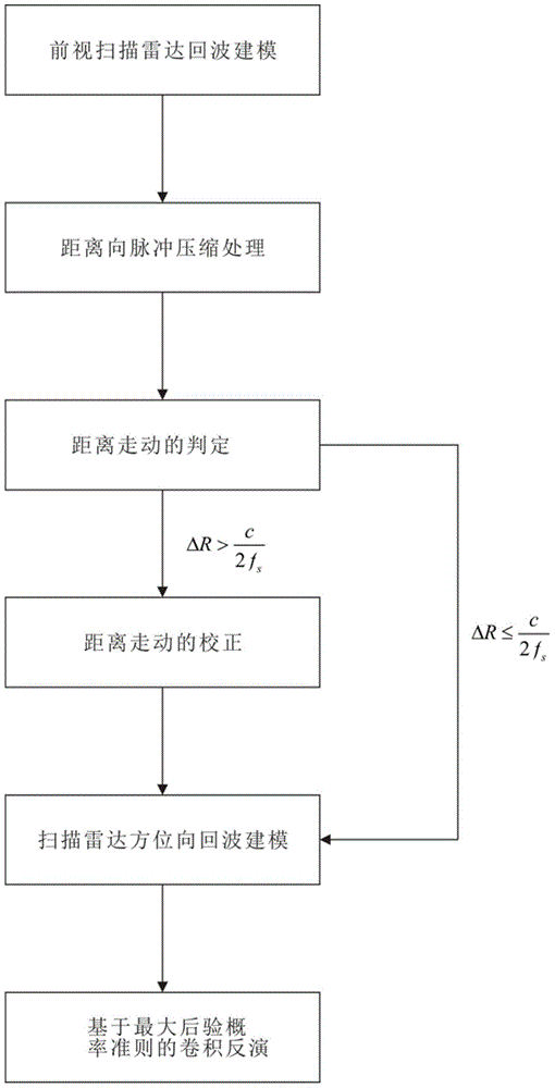
[0088] A deconvolution method for realizing scanning radar azimuth super-resolution imaging, comprising the following steps:

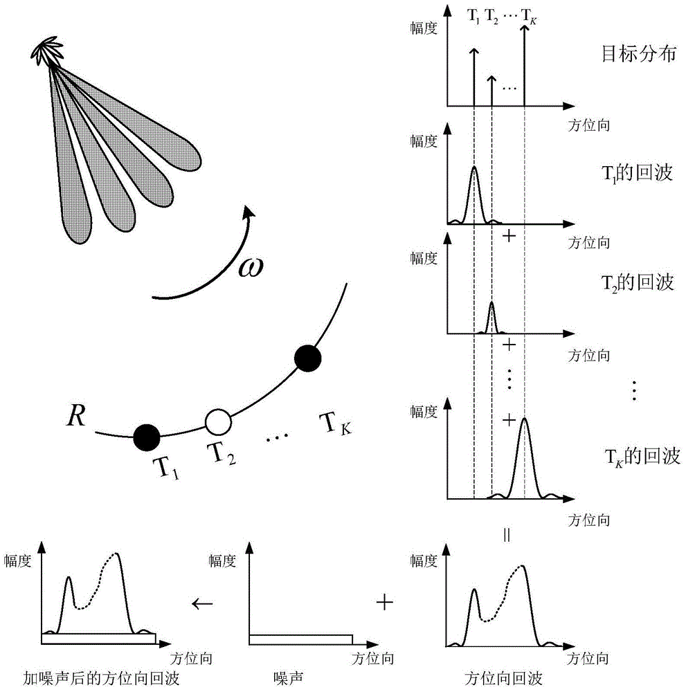
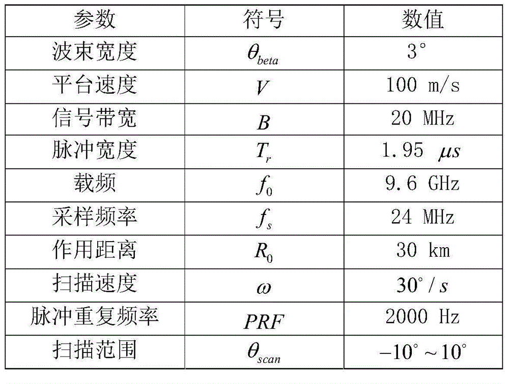
[0089] Step 1, forward-looking scanning radar echo modeling; said step 1 is to derive the distance history from the target to the radar antenna in the scene under the forward-looking condition according to the geometric relationship of the radar system and the process of signal transmission and reception, and establish the forward-looking echo time domain model. Attached figure 2 Geometric pattern of forward-looking scanning radar imaging motion shown. select image 3 Radar system parameters shown. The angle and amplitude information of the target used in the steps of this program is as follows: Figure 5 shown. according to figure 2 The forward-looking scanning radar imaging motion geometry model in image 3...


PUM


Abstract

The invention discloses a deconvolution method for realizing scanning radar azimuth super-resolution imaging. Step one, forward-looking scanning radar echo modeling is performed; step two, range direction pulse compression processing is performed; step three, range wall determination is performed; step four, range walk correction is performed; step five, scanning radar azimuth direction echo modeling is performed; and step six, convolution inversion based on the maximum posterior probability criterion is performed. The beneficial effects are that an azimuth echo convolution model is established, an algorithm iteration expression is derived based on the maximum posterior probability criterion through combination of prior information and a likelihood function, low frequency is reconstructed, high frequency is recovered, an iterative solution is obtained by utilizing frequency spectrum extrapolation property, a problem of spectrum loss caused by noise and antenna low-pass property is overcome, a high-frequency component is acquired by utilizing nonlinear operation separation and super-resolution imaging is realized. Besides, frequency domain spectrum width and a change trend diagram of frequency domain integral sidelobe comparison number of iterations are provided by utilizing the frequency spectrum extrapolation property, and finally convolution inversion is realized and the inversion result is used for realizing scanning radar super-resolution imaging.

Description

technical field [0001] The invention belongs to the technical field of radar imaging, and in particular relates to a scanning radar azimuth direction super-resolution imaging method. Background technique [0002] At present, radar forward-looking high-resolution imaging technology has a wide range of application requirements in both military and civilian applications. Realize high-resolution imaging of the forward-looking area of ​​the radar platform, which can be used in ground search, sea detection and imaging, long-distance reconnaissance, material airdrop, terrain matching, ground attack, terrain following, aircraft autonomous landing, missile terminal guidance and other fields play a huge role. [0003] Radar forward-looking high-resolution imaging requires high-resolution images in both range and azimuth directions. High resolution in the range direction can be achieved by transmitting a chirp signal with a large time-width-bandwidth product, and then processing the ...

Claims


Application Information

Patent Timeline
Patent Type & Authority Applications(China)
IPC IPC(8): G01S13/89
CPCG01S13/89
Inventor 黄钰林王月查月波任建宇蒲巍杨建宇
Owner UNIV OF ELECTRONICS SCI & TECH OF CHINA
Learn More