An engine chain timing system
A timing system and engine technology, applied in the directions of engine components, machines/engines, belts/chains/gears, etc., can solve the problems of increased system vibration, unfavorable engine fuel utilization, large friction loss of the timing system, etc. The effect of smooth and quiet movement, avoiding major quality accidents and improving fuel efficiency
Active Publication Date: 2017-07-21
BRILLIANCE AUTO
View PDF4 Cites 0 Cited by
- Summary
- Abstract
- Description
- Claims
- Application Information
AI Technical Summary
Problems solved by technology
[0002] The engine timing chain system (including the balance shaft chain system and the oil pump system) works in an environment with oil injection lubrication, and usually has a relatively high speed (the maximum speed of the balance shaft can reach 14000rpm). Wear and tear of components, the intake and exhaust time of the engine will change, resulting in a decrease in engine power. When the chain wears to a certain extent, it will also cause the tensioner to be completely protruded, lose the tensioning effect, and the vibration of the system will increase, and even The chain will jump teeth, the timing of intake and exhaust will be disordered, and in most cases, high-speed collision between the engine piston and valve will occur, and the engine will be damaged in an instant
[0003] The chain and sprocket of the existing engine timing chain system are made of steel. When the chain meshes with the sprocket at a very high speed, it will generate a lot of noise, which will deteriorate the NVH characteristics of the engine. This is why many engines still use belts. The reason is the timing system, but the timing belt has defects such as short service life and easy cracking. Therefore, if the noise of the chain drive system can be reduced, it can provide better support for the overall performance of the engine
[0004] Reducing the mechanical friction loss of the engine and improving the fuel utilization rate of the engine are important improvement directions for the design and manufacture of the engine. In order to reduce the vibration of the chain in the existing engine, it is necessary to add a guide rail to a certain part around the chain. However, due to the high-speed movement of the chain and There is sliding friction between the guide rails, which leads to a large friction loss in the timing system, which is not conducive to improving the fuel efficiency of the engine
Method used
View moreImage
Smart ImageViewing Examples

Examples
Embodiment 2
[0031] The difference between this embodiment and Embodiment 1 is that: a steel roller with a surface treated by carbonitriding is arranged outside the roller 3-1.
Login to View More PUM
 Abstract
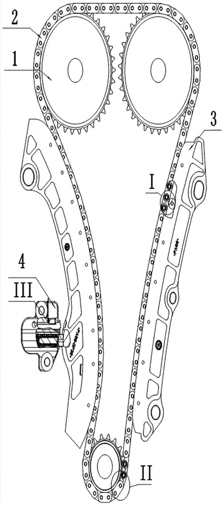
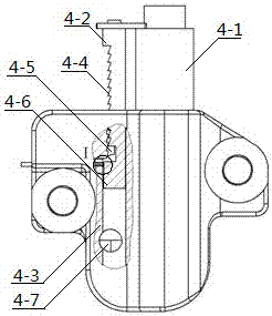
The invention relates to a device used for an engine and acting on a timing belt or chain, in particular to an engine chain timing system. A high-intensity nylon chain wheel structure is adopted, so that original steel-steel contact between a chain and chain wheels is converted into nylon-steel contact; oil-resistant rubber is arranged below the position, between every two adjacent teeth of the chain wheels, of the tooth root circle; in the process that the chain is pinched into the chain wheels, a chain connection board makes contact with the oil-resistant rubber firstly, and then rollers are pinched into the chain wheels, so that the pinching impact between the rollers and the chain wheels is greatly reduced, the NVH of the chain timing system is improved, and the system moves more stably and silently. Idler wheels are additionally arranged on a guide rail, so that sliding fiction between a chain plate on the chain and a guide rail in the prior art is changed into rolling friction between the rollers and the guide rail, the friction loss of the system is reduced, and the fuel utilization ratio of the engine is increased. A sensor used for detecting whether a plunger bounces up completely or not is also additionally arranged in an expansion machine and can remind a driver of replacing the chain timing system in time, and major quality accidents of the engine are avoided.
Description
technical field [0001] The invention relates to a device acting on a timing belt or chain for an engine, in particular to an engine chain timing system. Background technique [0002] The engine timing chain system (including the balance shaft chain system and the oil pump system) works in an environment with oil injection lubrication, and usually has a relatively high speed (the maximum speed of the balance shaft can reach 14000rpm). Wear and tear of components, the intake and exhaust time of the engine will change, resulting in a decrease in engine power. When the chain wears to a certain extent, it will also cause the tensioner to be completely protruded, lose the tensioning effect, and the vibration of the system will increase, and even As a result, the chain jumps teeth, the timing of intake and exhaust is disordered, and in most cases, high-speed collision between the engine piston and valve will occur, and the engine will be damaged in an instant. [0003] The chain a...
Claims
Login to View More Application Information
Patent Timeline
 Patent Type & Authority Patents(China)
IPC IPC(8): F01L1/348F16H55/30F16H7/08
CPCF01L1/348F16H7/08F16H55/30F16H2007/087
Inventor 董其超黄昌瑞李振华邢建恒
Owner BRILLIANCE AUTO