

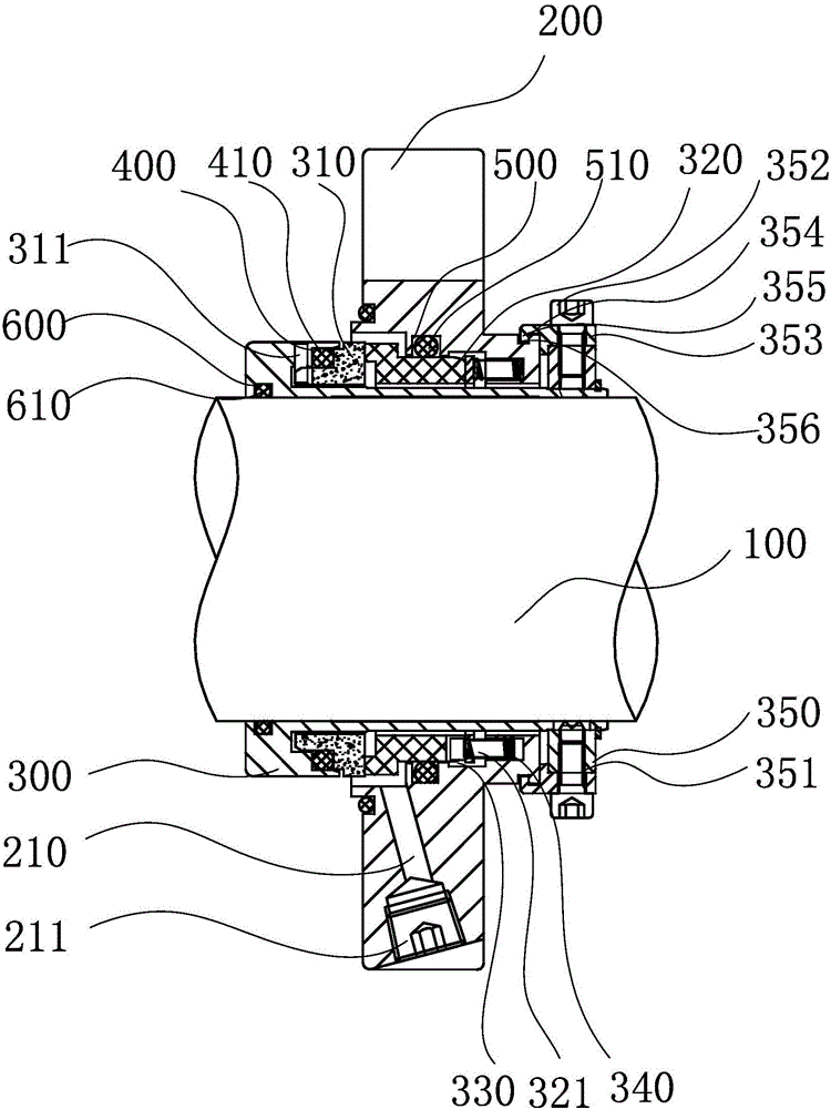
Mechanical seam with improved structure
A mechanical seal and improved structure technology, which is applied in the direction of engine seal, mechanical equipment, engine components, etc., can solve the problems of reducing the service life of the moving ring and the static ring, damage of the moving ring and the static ring, and general sealing effect, so as to improve Effects of service life, reduction of surface temperature, and improvement of wear resistance
- Summary
- Abstract
- Description
- Claims
- Application Information
AI Technical Summary
Problems solved by technology
Method used
Image

Examples
Embodiment 1
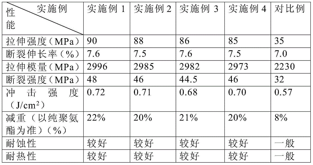
[0039] The raw materials are weighed according to the following parts by weight: polyurethane: 100 parts, epoxy resin: 20 parts, hydroxylated multi-walled carbon nanotubes: 2 parts, nano-titanium dioxide with a particle size of 40nm: 2 parts, fatty acid and its ester lubricant : 1 part, POE-g-MAH: 2 parts, hindered phenolic antioxidant: 3 parts, alkane sulfonic acid: 2 parts, wherein, the hydroxylated multi-walled carbon nanotubes are made of polyethylene glycol by the azide method Alcohol and pentaerythritol were grafted onto multi-walled carbon nanotubes to prepare hydroxylated multi-walled carbon nanotubes.
[0040] Put the raw materials in the above ratio into the compounding machine and mix them evenly, then pour them into the extruder to melt, extrude, and pelletize the composite material, then put the composite material into the mold frame for hot-press plasticization, hot-press The finished grinding frame is cold-pressed and formed. After the cold-pressing is completed...
Embodiment 2
[0042] Weigh raw materials according to the following parts by weight: polyurethane: 100 parts, epoxy resin: 22 parts, hydroxylated multi-walled carbon nanotubes: 1 part, nano-titanium dioxide with a particle size of 30nm: 1 part, fatty acid amide: 2 parts, phenolic Resin: 3 parts, phosphite antioxidant: 5 parts, alkylsulfonic acid: 2 parts, wherein, polyethylene glycol and pentaerythritol are respectively grafted to the hydroxylated multi-walled carbon nanotubes by the azide method Hydroxylated multi-walled carbon nanotubes were prepared on the multi-walled carbon nanotubes.
[0043] Put the raw materials in the above ratio into the compounding machine and mix them evenly, then pour them into the extruder to melt, extrude, and pelletize the composite material, then put the composite material into the mold frame for hot-press plasticization, hot-press The finished grinding frame is cold-pressed and formed. After the cold-pressing is completed, the rough product of the sealing ...
Embodiment 3
[0045] The raw materials are weighed according to the following parts by weight: polyurethane: 100 parts, epoxy resin: 25 parts, hydroxylated multi-walled carbon nanotubes: 1 part, nano-titanium dioxide with a particle size of 60 nm: 3 parts, organosilicon compound: 0.5 parts, Silane coupling agent: 0.5 parts, hindered amine antioxidant: 2 parts, alkali metal salt of dithiocarbamic acid: 0.5 parts, wherein, the hydroxylated multi-walled carbon nanotubes are synthesized from polyethylene by azide method Diol and pentaerythritol were grafted onto multi-walled carbon nanotubes respectively to prepare hydroxylated multi-walled carbon nanotubes.
[0046] Put the raw materials in the above ratio into the compounding machine and mix them evenly, then pour them into the extruder to melt, extrude, and pelletize the composite material, then put the composite material into the mold frame for hot-press plasticization, hot-press The finished grinding frame is cold-pressed and formed. After...
PUM
| Property | Measurement | Unit |
|---|---|---|
| particle diameter | aaaaa | aaaaa |
Abstract
Description
Claims
Application Information