Alarm device for monitoring partial overtemperature of kiln nozzle

An alarm device and kiln technology, which is applied to furnaces, furnace components, lighting and heating equipment, etc., can solve problems such as burnout temperature resistance, difficulty in automatic monitoring, and difficulty in designing supporting monitoring devices, so as to prevent equipment damage and reduce Effects of maintenance difficulty and cost

Active Publication Date: 2015-10-21
MODENA TECH LTD
View PDF7 Cites 0 Cited by
  • Summary
  • Abstract
  • Description
  • Claims
  • Application Information

AI Technical Summary

Problems solved by technology

Since the combustion chamber of the burner is built in the insulation layer of the wall and the temperature is high, it is difficult to monitor automatically, and it is not easy to detect when there is a problem. Most of the time, the kiln body in the burner area is burned out until the panel is blackened, red or goes out. It can only be discovered when the fire escapes. At this time, huge losses have been caused, and it is necessary to shut down the kiln for maintenance.
[0003] Directly monitor the combustion chamber. Due to the influence of structural sealing and high temperature, it is difficult to design a supporting monitoring device. At present, it mainly relies on the operator to continuously patrol, which is labor-intensive and needs to be discovered after the kiln wall in the burner area is obviously damaged.
The kiln wall generally uses refractory materials of different temperature grades from the fire-seeing surface to the outside of the wall. The closer to the outer wall, the smaller the thermal conductivity but the lower the temperature resistance. Therefore, when the combustion chamber cracks or breaks, the flame will Burn out the insulation material with low temperature resistance, resulting in fire escape

Method used


Image

  • Alarm device for monitoring partial overtemperature of kiln nozzle
  • Alarm device for monitoring partial overtemperature of kiln nozzle
  • Alarm device for monitoring partial overtemperature of kiln nozzle

Examples


Embodiment Construction

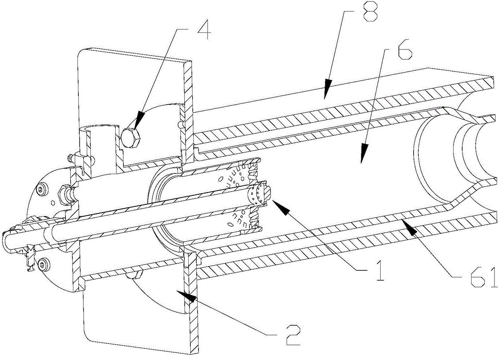
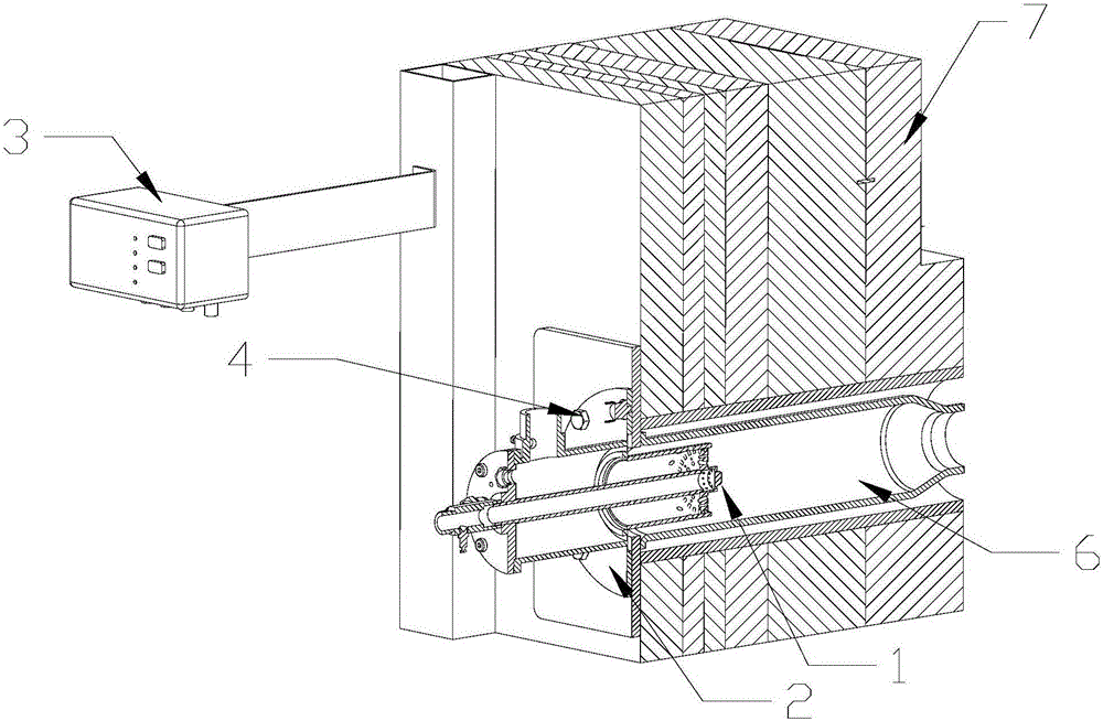
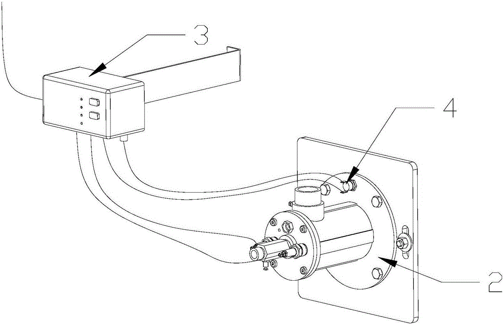
[0015] Such as Figure 1-Figure 4 As shown, a local overtemperature alarm device for monitoring kiln burners according to an embodiment of the present invention

[0016] It includes a burner 1, a burner flange 2, a burner controller 3, and a temperature sensing element 4; among them, the burner 1 has an ignition electrode and a monitoring electrode, and the burner flange 2 is installed on the kiln 5 and is close to the burning On the outer wall, a burner combustion chamber 6 is arranged around the burner 1, and the burner combustion chamber 6 is composed of a pipe sleeve 61 made of silicon carbide, and an insulating layer installed on the kiln 5 is also provided outside the pipe sleeve 61 made of silicon carbide The high aluminum protective cover 8 in 7; the temperature sensing element 4 is a contact temperature sensing element installed on the burner flange 2, and transmits the temperature signal to the burner controller 3. The burner controller 3 is used to control ignition...


PUM


Abstract

The invention relates to a kiln auxiliary alarm device, in particular to an alarm device for monitoring partial overtemperature of a kiln nozzle. The alarm device comprises a nozzle, a nozzle flange, a nozzle controller and a temperature sensing element. The nozzle is provided with an ignition electrode and a monitoring electrode. The nozzle flange is arranged on a kiln and attached to the outer wall of a combustion chamber. A nozzle combustion chamber is arranged around the nozzle and composed of a pipe sleeve made of a silicon carbide material. A high-aluminum protection cover is further arranged outside the pipe sleeve which is made of the silicon carbide material and is located in an insulated layer of the kiln. The temperature sensing element is a touch type temperature sensing element located on the nozzle flange and transmits temperature signals to the nozzle controller. The temperature of the area around the nozzle is detected through the temperature sensing element, when the temperature exceeds a normal range, the nozzle controller sends out an alarm signal to remind an operator to check the nozzle in time, the condition that the kiln and equipment are damaged when the temperature is ultrahigh is prevented, and therefore maintenance difficulty and cost are effectively reduced.

Description

technical field [0001] The invention relates to an auxiliary alarm device for a kiln, in particular to an alarm device for monitoring local overtemperature of a burner of a kiln. Background technique [0002] During the working process of the kiln, the burner combustion chamber with continuous heating is in a high temperature state for a long time, and the product volume is difficult to be stable all the time. The temperature of the burner combustion chamber is constantly changing. Due to repeated lifting and lowering, or multiple ignition and extinguishing, the fire-seeing surface of the combustion chamber is always in a state of expansion and contraction. When the partial shrinkage is inconsistent or exceeds the life of its material, the combustion chamber of the burner will crack or even break. Since the combustion chamber of the burner is built in the insulation layer of the wall and the temperature is high, it is difficult to monitor automatically, and it is not easy t...

Claims


Application Information

Patent Timeline
IPC IPC(8): F27D21/04
Inventor 管火金梁钊林熊亮荆海山陶志坚程希如
Owner MODENA TECH LTD
Why Eureka
Try Eureka