Method and device for performing weak magnetic control on permanent-magnet brushless direct-current motor

A permanent magnet brushless DC and field-weakening control technology, which is applied in the direction of motor generator control, electromechanical transmission control, electronic commutation motor control, etc., can solve the problems of inability to provide energy to the motor, saturation of field-weakening current, and out-of-control of field-weakening current And other issues

Active Publication Date: 2015-10-21
GD MIDEA AIR-CONDITIONING EQUIP CO LTD +1
View PDF6 Cites 11 Cited by
  • Summary
  • Abstract
  • Description
  • Claims
  • Application Information

AI Technical Summary

Problems solved by technology

But in the non-electrolytic capacitor driver, the DC bus voltage fluctuates sinusoidally, and, with the increase of the motor operating frequency and power, the minimum value of the DC bus voltage begins to decrease, when the minimum value of the DC bus voltage is less than the motor When the back electromotive force is applied, the DC bus voltage cannot provide energy for the motor
Therefore, in order to maximize the use of the DC bus voltage to provide energy for the motor, the field weakening control is performed within the entire motor operating frequency and power range. At the trough of the DC bus voltage, the actual voltage vector will exceed the regular hexagon of the voltage vector. If the traditional field-weakening control method is adopted, the field-weakening current will be saturated, which will cause the field-weakening current to run out of control

Method used


Image

  • Method and device for performing weak magnetic control on permanent-magnet brushless direct-current motor
  • Method and device for performing weak magnetic control on permanent-magnet brushless direct-current motor
  • Method and device for performing weak magnetic control on permanent-magnet brushless direct-current motor

Examples


Embodiment Construction

[0028] Embodiments of the present invention are described in detail below, examples of which are shown in the drawings, wherein the same or similar reference numerals designate the same or similar elements or elements having the same or similar functions throughout. The embodiments described below by referring to the figures are exemplary and are intended to explain the present invention and should not be construed as limiting the present invention.

[0029] The field weakening control method of the permanent magnet brushless DC motor and the field weakening control device of the permanent magnet brushless DC motor according to the embodiments of the present invention will be described below with reference to the accompanying drawings.

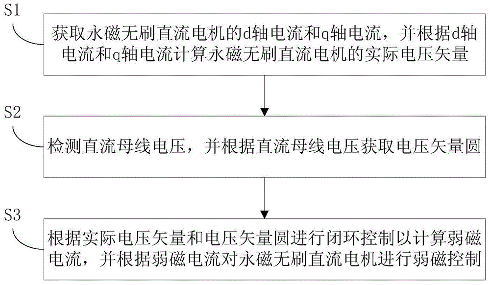
[0030] figure 1 It is a flow chart of a method for field weakening control of a permanent magnet brushless direct current motor according to an embodiment of the present invention, wherein there is no electrolytic capacitor in the motor contro...


PUM


Abstract

The invention discloses a method and a device for performing weak magnetic control on a permanent-magnet brushless direct-current motor. The method comprises the following steps: acquiring the d-axis current and q-axis current of a permanent-magnet brushless direct-current motor, and calculating the actual voltage vector of the permanent-magnet brushless direct-current motor according to the d-axis current and the q-axis current; detecting the direct-current bus voltage, and acquiring a voltage vector circle according to the direct-current bus voltage; and performing closed-loop control according to the actual voltage vector and the voltage vector circle to calculate the weak magnetic current, and performing weak magnetic control on the permanent-magnet brushless direct-current motor according to the weak magnetic current, wherein weak magnetic control is effective when the absolute value of the actual voltage vector V1 is smaller than the quotient of the direct-current bus voltage Vdc and the square root of 3. By adopting the method, weak magnetic control can be stopped when the actual voltage vector of the motor is beyond the voltage vector circle, so that the problem of weak magnetic current out-of-control caused by weak magnetic current saturation is solved effectively.

Description

technical field [0001] The invention relates to the technical field of motors, in particular to a field-weakening control method for a permanent magnet brushless direct current motor and a field weakening control device for a permanent magnet brushless direct current motor. Background technique [0002] With the improvement of users' energy-saving requirements for electromechanical products, variable frequency motor drives with higher efficiency have been more and more widely used. [0003] Usually, the DC bus voltage of the variable frequency motor driver is in a stable state, and the inverter part is relatively independent from the input AC voltage such as the grid voltage, so that the control of the inverter part does not need to consider the instantaneous change of the input AC voltage, which is convenient for the realization of the control method. In order to ensure that the DC bus voltage is in a stable state, an electrolytic capacitor with a large capacitance is usual...

Claims


Application Information

Patent Timeline
Patent Type & Authority Applications(China)
IPC IPC(8): H02P21/06
Inventor 肖有文
Owner GD MIDEA AIR-CONDITIONING EQUIP CO LTD
Why Eureka
Try Eureka