
A blood vessel automatic thrombolysis system

A technology of thrombolysis and blood vessels, applied in medical science, surgery, suction equipment, etc., can solve the problems of unstable thrombolysis speed, unstable effect, plaque shedding, etc., and achieve precise and controllable dosage and suction volume , easy to objectively evaluate the curative effect, and realize the effect of objective evaluation of the curative effect

Inactive Publication Date: 2019-11-15
XUANWU HOSPITAL OF CAPITAL UNIV OF MEDICAL SCI +2
View PDF5 Cites 0 Cited by
  • Summary
  • Abstract
  • Description
  • Claims
  • Application Information

AI Technical Summary

Problems solved by technology

[0003] 1. Due to the small diameter of the guide wire and the large viscous resistance of the liquid, the pushing and pulling force required to push and pull the syringe piston is relatively large, and repeated pushing and pulling by hand for a long time is prone to fatigue;
[0004] 2. Repeated manual push-pull operation is not easy to accurately control the flow rate of each wave, resulting in unstable thrombolytic speed, and when the impact force is too large, the plaque may even fall off and cause obstruction
[0005] 3. The push-pull time of each wave cannot be precisely controlled, which can also cause unstable thrombolysis speed
[0006] 4. Manual operation is limited by the operator's skills, physical strength and subjectivity, so that the operation process cannot be standardized, and the effect of thrombolysis operation varies greatly from person to person, and the effect is unstable

Method used


Image

  • A blood vessel automatic thrombolysis system
  • A blood vessel automatic thrombolysis system
  • A blood vessel automatic thrombolysis system

Examples


Embodiment Construction

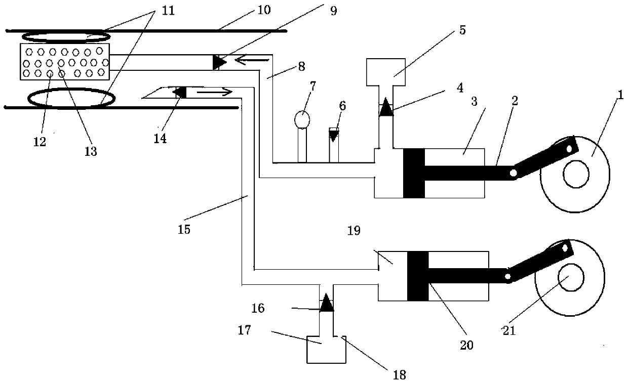
[0039] An automatic blood vessel thrombolysis system is characterized in that the system includes two parts: a liquid medicine pushing system and a suction system.

[0040] In the above system, the medicinal liquid pushing part includes a medicinal liquid pushing pump body 1, which is used to provide the power required for pushing the medicinal liquid; to the thrombus site; the liquid medicine pushing pump piston cylinder 3 is used to hold the liquid medicine to be pushed into the thrombus site; the medicine liquid check valve 4 is used to control the opening of the medicine liquid when the piston carries out the suction stroke, so as to inhale the medicine liquid to the thrombus site. The piston cylinder is closed during the push stroke to prevent the thrombolytic drug liquid from flowing reversely to the thrombolytic drug liquid replenishment chamber; the medicinal liquid replenishment chamber 5 is used to hold the medicinal liquid to be pushed into the thrombus; the overpres...


PUM


Abstract

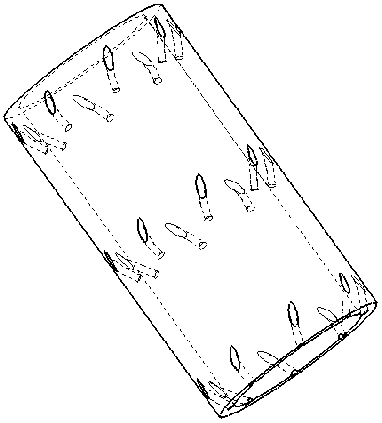
The invention relates to an automatic blood vessel thrombolysis system. The automatic blood vessel thrombolysis system is characterized by comprising a liquid medicine pushing part and a liquid medicine suction part. The liquid medicine pushing system mainly comprises a pushing pump, a pushing pipeline provided with a spiral liquid outlet, a non-return valve, a liquid medicine supplement cavity and the like, and the liquid medicine suction system mainly comprises a suction pump, a suction pipeline, a non-return valve, a discharge container and the like. When the automatic blood vessel thrombolysis system works, the liquid medicine pushing system draws thrombolysis liquid medicine, and pushes the thrombolysis liquid medicine into the pushing pipeline, and injects the thrombolysis liquid medicine to the thrombus position through the spiral liquid outlet. After a certain thrombolysis period of time, the liquid medicine suction system works, thrombus dissolved matter generated by the thrombolysis process and residual liquid medicine are absorbed by the suction pump through the suction pipeline and the non-return valve, then the suction pump pushes the thrombus dissolved matter and the residual liquid medicine to the discharge container, and a circular thrombolysis operation is completed. According to the embolism case, the above thrombolysis process is repeated. The automatic blood vessel thrombolysis system can achieve automatic operation of thrombolysis, and can control injection and suction of thrombolytics accurately, and can guarantee standardization of thrombolysis surgery.

Description

technical field [0001] The invention relates to an automatic blood vessel thrombolysis system, in particular to the field of heart, brain and peripheral blood vessel thrombolysis treatment. Background technique [0002] The incidence of heart, brain, and peripheral vascular diseases continues to increase. At present, most of them are treated with thrombolytic drugs. For more severely blocked blood vessels, thrombolytic injection is often used clinically. The devices used are auxiliary devices such as interventional guide wires, catheters, and syringes. Through the superficial blood vessels, under the guidance of the interventional guide wire, guide the catheter to the thrombus site, and then use the repeated pulling action of the syringe plunger to repeatedly flush the thrombus with a thrombolytic agent to achieve the purpose of rapid thrombolysis. There are following problems and deficiencies in this method: [0003] 1. Due to the small diameter of the guide wire and the ...

Claims


Application Information

Patent Timeline
Patent Type & Authority Patents(China)
IPC IPC(8): A61B17/22A61M1/00
Inventor 吉训明闫健卓刘晓民方滨郎野李思颉陈健苏伟
Owner XUANWU HOSPITAL OF CAPITAL UNIV OF MEDICAL SCI
Learn More