Top drive type drilling machine system based on dynamic control of tool surface of underground drilling tool and well drilling method

A technology of dynamic control and tool face, applied in drilling automatic control system, drilling equipment and method, drilling equipment, etc. to improve control accuracy and operation efficiency, improve wellbore quality, and correct drift

Active Publication Date: 2015-10-28
CHINA NAT OFFSHORE OIL CORP +1
View PDF10 Cites 7 Cited by
  • Summary
  • Abstract
  • Description
  • Claims
  • Application Information

AI Technical Summary

Problems solved by technology

However, under the conditions of formation lithology changes, mud flow changes and drill bit wear, the tool face of the dynamic drilling tool is prone to deviation, causing the actual wellbore to deviate from the designed trajectory
At present, the general method to deal with this problem is to lift the drill after stopping drilling and readjust the downhole motor to make the tool face of the downhole motor point to the correct position, but this method reduces the efficiency of drilling operations
The tool face of the downhole drilling tool can be measured in real time by using the measurement while drilling equipment, and the direction of the tool face of the downhole dynamic drilling tool can be adjusted or corrected by rotating the top drive or the rotary table according to the measurement results, but due to the drill string system in the measurement while drilling equipment Long and extensive drill string system contact with the borehole wall, making it difficult to determine the angle required to turn the top drive or rotary table

Method used


Image

  • Top drive type drilling machine system based on dynamic control of tool surface of underground drilling tool and well drilling method
  • Top drive type drilling machine system based on dynamic control of tool surface of underground drilling tool and well drilling method
  • Top drive type drilling machine system based on dynamic control of tool surface of underground drilling tool and well drilling method

Examples


Embodiment Construction

[0019] The present invention will be described in detail below in conjunction with the accompanying drawings and embodiments.

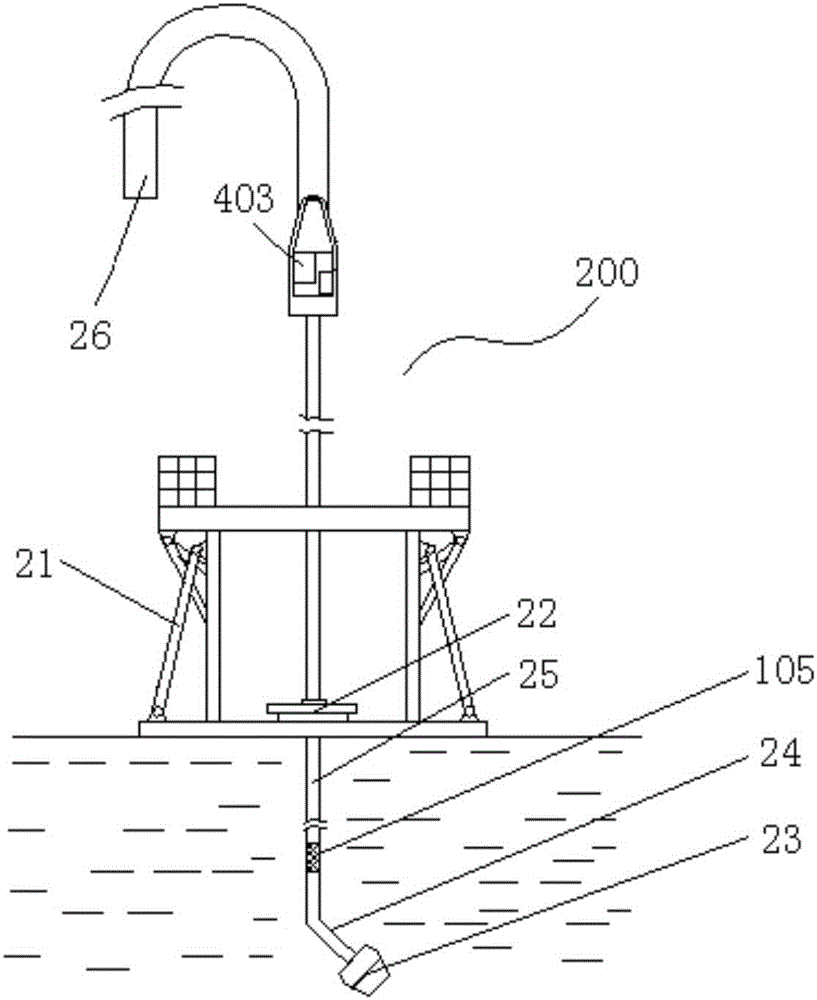
[0020] Such as figure 1 , figure 2 As shown, the drilling rig system of the present invention includes a dynamic control system 100 and a drilling system 200 .

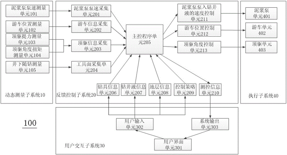
[0021] Such as figure 1 As shown, the dynamic control system 100 includes a dynamic measurement subsystem 10 , a feedback control subsystem 20 , a user interaction subsystem 30 and an execution subsystem 40 .

[0022] Among them, the dynamic measurement unit subsystem 10 includes a mud pump speed measurement unit 101 , a traveling block position measurement unit 102 , a top drive lifting force measurement unit 103 , a top drive angle torque measurement unit 104 and a downhole measurement unit 105 while drilling.

[0023] Feedback control subsystem 20 includes mud pump pump speed acquisition unit 201, traveling block information acquisition unit 202, top drive information acquisition unit ...


PUM


Abstract

The invention relates to a top drive type drilling machine system based on dynamic control of a tool surface of an underground drilling tool and a well drilling method. The drilling machine system comprises a dynamic control system and a well drilling system, wherein the dynamic control system comprises a dynamic measuring subsystem, a feedback control subsystem, a user interaction subsystem and an execution subsystem; a user inputs drilling tool information, well drilling fluid information, stratum information and a control strategy through the user interaction subsystem; a many-body dynamics model of a well drilling system is established by the feedback control subsystem according to the received drilling tool information, well drilling fluid information and stratum information; various information of the well drilling system in a well drilling process is measured by the dynamic measuring subsystem and is transferred to the feedback control subsystem; and the feedback control subsystem judges whether the tool surface of the underground drilling tool exceeds a set threshold value or not, calculates the required rotating angle of a top drive, the position of a traveling block and the pumping speed of a slurry pump in a many-body dynamics simulating manner, and drives the top drive, the traveling block and the slurry pump to run. The top drive type drilling machine system continues drilling until the tool surface of the underground drilling tool returns to a design position, and dynamic adjustment control on the tool surface of the underground drilling tool is finished.

Description

technical field [0001] The invention relates to an oil and gas field drilling rig system and a drilling method, in particular to a top drive drilling rig system and a drilling method based on a multi-body dynamics model for dynamic control of the tool face of a downhole drilling tool. Background technique [0002] Sliding steerable drilling is a common method for directional drilling operations, which uses downhole angled power drilling tools to build deflection. However, under the conditions of formation lithology changes, mud flow changes and drill bit wear, the tool face of the dynamic drilling tool is prone to deviation, causing the actual wellbore to deviate from the designed trajectory. At present, the general method to deal with this problem is to lift the drill after stopping the drilling and readjust the downhole motor so that the tool face of the downhole motor points to the correct position. However, this method reduces the efficiency of drilling operations. The ...

Claims


Application Information

Patent Timeline
IPC IPC(8): E21B7/04E21B7/08E21B44/00
Inventor 周建良刘书杰何保生李汉兴曹砚锋程载斌武广瑷李峰飞
Owner CHINA NAT OFFSHORE OIL CORP
Why Eureka
Try Eureka