Dynamic control system and dynamic control method for underground directional power drill tool surface

A dynamic control and tool face technology, applied in the automatic control system of drilling, directional drilling, drilling equipment, etc., can solve problems such as difficulty in determining the angle of the rotating top drive or turntable, reducing the efficiency of drilling operations, and the deviation of power drilling tools , to achieve the effect of improving control accuracy and operation efficiency, improving wellbore quality, and correcting drift

Active Publication Date: 2015-10-28
CHINA NAT OFFSHORE OIL CORP +1
View PDF7 Cites 4 Cited by
  • Summary
  • Abstract
  • Description
  • Claims
  • Application Information

AI Technical Summary

Problems solved by technology

However, under the conditions of formation lithology changes, mud flow changes and drill bit wear, the tool face of the dynamic drilling tool is prone to deviation, causing the actual wellbore to deviate from the designed trajectory
At present, the general method to deal with this problem is to lift the drill after stopping drilling and readjust the downhole motor to make the tool face of the downhole motor point to the correct position, but this method reduces the efficiency of drilling operations
The tool face of the dow

Method used


Image

  • Dynamic control system and dynamic control method for underground directional power drill tool surface
  • Dynamic control system and dynamic control method for underground directional power drill tool surface
  • Dynamic control system and dynamic control method for underground directional power drill tool surface

Examples


Embodiment 1

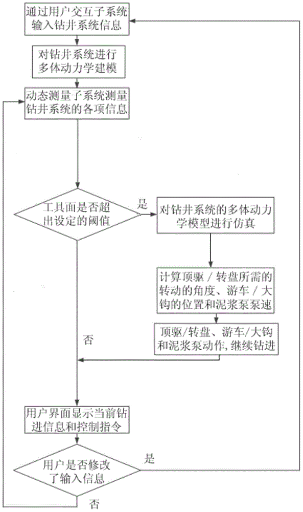
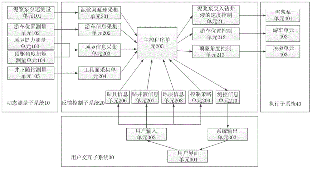
[0022] Such as figure 1 As shown, when the top drive is used for drilling, the dynamic measurement unit subsystem 10 includes a mud pump speed measurement unit 101, a traveling block position measurement unit 102, a top drive lifting force measurement unit 103, a top drive angle torque measurement unit 104 and Downhole measurement while drilling unit 105 .

[0023] Feedback control subsystem 20 includes mud pump pump speed acquisition unit 201, traveling block information acquisition unit 202, top drive information acquisition unit 203, tool face acquisition unit 204, main control program unit 205, drilling tool information unit 206, drilling fluid information unit 207 , formation information unit 208 , control strategy unit 209 , measurement and control information unit 210 , speed control unit 211 for mud pump pumping drilling fluid, traveling block position control unit 212 and top drive angle control unit 213 . Wherein, the output ends of the mud pump speed measuring unit...

Embodiment 2

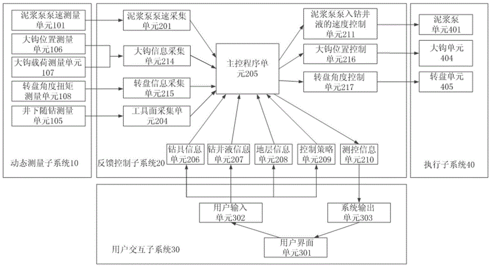
[0028] Such as figure 2 As shown, when the rotary table is used for drilling, the principle and structure of the dynamic control system for the tool face of the downhole directional dynamic drilling tool implemented in this implementation are similar to those of the top drive for drilling, the difference is that:

[0029] In the dynamic measurement unit subsystem 10, the hook position measurement unit 106 is used to replace the traveling block position measurement unit 102, the hook load measurement unit 107 is used to replace the top drive lifting force measurement unit 103, and the turntable angle torque measurement unit 108 is used to replace the top drive angle The torque measuring unit 104 and other units are the same as those in the first embodiment.

[0030] In the feedback control subsystem 20, the hook information collection unit 214 that is electrically connected to the hook position measurement unit 106 and the hook load measurement unit 107 is used to replace the ...


PUM


Abstract

The invention relates to a dynamic control system and a dynamic control method for an underground directional power drill tool surface. The dynamic control system comprises a dynamic measurement sub system, a feedback control sub system, a user interaction sub system and an execution sub system, wherein a user inputs drill tool information, drilling fluid information, stratum information and control strategies through the user interaction sub system; the feedback control sub system builds a many-body dynamics model of a drilling system according to the received drilling tool information, the drilling fluid information and the stratum information; the dynamic measurement sub system measures various kinds of information of the drilling system in the drilling process and transmits the information to the feedback control sub system; the feedback control sub system judges whether the drill tool surface exceeds a set threshold or not; the rotating angle required by a top drive/turntable, the position of a traveling block/large hook and the pump speed of a slurry pump are calculated through many-body dynamics simulation; the top drive/turntable, the traveling block/large hook and the slurry pump are driven to act; the drilling is continuously carried out so that the underground drill tool surface returns to the design position; and the dynamic regulation control on the underground drill tool surface is completed.

Description

technical field [0001] The invention relates to a control system and method of an oil and gas field downhole drilling tool, in particular to a dynamic control system and method for a downhole directional dynamic drilling tool face based on a multi-body dynamic model. Background technique [0002] Sliding steerable drilling is a common method for directional drilling operations, which uses downhole angled power drilling tools to build deflection. However, under the conditions of formation lithology changes, mud flow changes and drill bit wear, the tool face of the dynamic drilling tool is prone to deviation, causing the actual wellbore to deviate from the designed trajectory. At present, the general method to deal with this problem is to lift the drill after stopping the drilling and readjust the downhole motor so that the tool face of the downhole motor points to the correct position. However, this method reduces the efficiency of drilling operations. The tool face of the d...

Claims


Application Information

Patent Timeline
IPC IPC(8): E21B44/00E21B7/04
Inventor 姜伟程载斌何保生王平双曹砚锋周建良李汉兴武广瑷李峰飞
Owner CHINA NAT OFFSHORE OIL CORP
Why Eureka
Try Eureka