Marine exhaust denitration system

An exhaust gas and denitration technology, applied in the field of ship exhaust gas denitration system, can solve problems such as large power consumption, rapid aging of electric heating equipment, condensation, etc., to avoid sulfuric acid condensation, reduce equipment corrosion, and improve the effect of denitration efficiency.

Active Publication Date: 2015-10-28
SUNRUI MARINE ENVIRONMENT ENG
View PDF8 Cites 15 Cited by
  • Summary
  • Abstract
  • Description
  • Claims
  • Application Information

AI Technical Summary

Problems solved by technology

For a ship using SCR technology, when sailing from a non-ECA area to an ECA area, the temperature in the SCR reactor is too low to meet the temperature required for the denitrification reaction; at the same time, due to the sealing problem of the valve, some exhaust gas may leak Entering the SCR reactor, if the SCR reactor is in a low temperature state for a long time, it will caus

Method used


Image

  • Marine exhaust denitration system
  • Marine exhaust denitration system
  • Marine exhaust denitration system

Examples


Embodiment 1

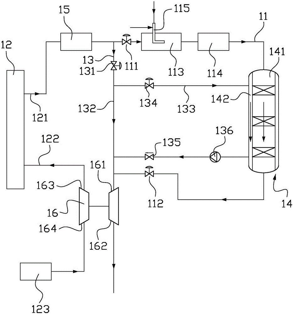
[0038] For a 72000DWT bulk carrier, the main engine power is 8000kw, the exhaust gas flow rate is 60000kg / h, and the nitrogen oxide content is 13g / kwh. Using the ship exhaust gas denitrification system of the present invention, the nitrogen oxide content of the treated exhaust gas can reach below 3g / kwh, which can meet the emission requirements of IMO for nitrogen oxides. At the same time, the power consumption saved by preheating and heat preservation of the denitrification reactor is 15kw, and no corrosion caused by sulfuric acid condensation has been found.

Embodiment 2

[0040] For a 150,000DWT crude oil tanker, the main engine power is 15,000kw, the exhaust gas flow rate is about 130,000kg / h, and the nitrogen oxide content is 13.8g / kwh. Using the ship exhaust gas denitrification system of the present invention, the nitrogen oxide content of the treated exhaust gas can reach below 3.2g / kwh, which can meet the emission requirements of IMO for nitrogen oxides. At the same time, the power consumption saved by preheating and heat preservation of the denitrification reactor is 32kw, and no corrosion caused by sulfuric acid condensation has been found.

Embodiment 3

[0042] For a 2000TEU container ship, the main engine power is 17000kw, the exhaust gas flow rate is 150000kg / h, and the nitrogen oxide concentration is 12g / kwh. Using the ship exhaust gas denitrification system of the present invention, the nitrogen oxide content of the treated exhaust gas can reach below 3g / kwh, which can meet the emission requirements of IMO for nitrogen oxides. At the same time, the power consumption saved by preheating and heat preservation of the denitrification reactor is 35kw, and no corrosion caused by sulfuric acid condensation has been found.


PUM


Abstract

A marine exhaust denitration system comprises an exhaust denitration pipe, an exhaust direct-discharging pipe and a denitration reactor. The exhaust denitration pipe is connected with the exhausting end of a diesel engine through a first valve. The exhaust direct-discharging pipe is connected with the exhausting end of the diesel engine through a second valve, and comprises a main exhaust direct-discharging pipe and an exhaust direct-discharging branch. The denitration reactor comprises a reaction chamber and an exhaust channel. The reaction chamber is connected to the interior of the exhaust denitration pipe. The exhaust channel is connected to the interior of the exhaust direct-discharging branch. When the first valve is opened and the second valve is closed, exhaust passes through the exhaust denitration pipe, is denitrated in the reaction chamber and then is discharged; when the first valve is closed and the second valve is opened, part of exhaust is discharged out of the main exhaust direct-discharging pipe, and the rest of exhaust enters the exhaust channel of the denitration reactor via the exhaust direct-discharging branch to maintain the temperature of the reactor. By means of the exhaust channel and the exhaust direct-discharging branch, the exhaust conducts preheating and temperature maintaining on the reaction chamber of the denitration reactor, and energy consumption can be reduced.

Description

technical field [0001] The invention relates to the field of atmospheric environment protection, in particular to a ship exhaust gas denitrification system. Background technique [0002] According to the requirements of the amendments to the Regulations for the Prevention of Air Pollution from Ships in Annex VI of the MARPOL 73 / 78 Convention adopted by the International Maritime Organization (IMO), the nitrogen oxides in the exhaust gas of ships must be treated to meet the standards before they can be discharged. For low-speed marine diesel engines (speed n<130rpm), the nitrogen oxide content after treatment should be less than 3.4g / kwh, but for current low-speed diesel engines, this emission requirement cannot be met only by optimizing the combustion method of diesel engines. Therefore, marine diesel engines must be equipped with marine exhaust gas denitrification systems, and Selective Catalytic Reduction (SCR) technology is currently the most applicable diesel engine p...

Claims


Application Information

Patent Timeline
IPC IPC(8): F01N3/28F01N5/02F02B37/00B01D53/92B01D53/94B01D53/56
CPCY02T10/12
Inventor 范昊刘光洲高健于航张文涛
Owner SUNRUI MARINE ENVIRONMENT ENG
Why Eureka
Try Eureka