Pasty propellant fuel gas generator ignition device based on solid rocket engine
A gas generator and paste propellant technology, which is applied in rocket engine devices, jet propulsion devices, machines/engines, etc., can solve the problem that the ignition reliability of the igniter is relatively high, the ignition process is difficult to control, and the ignition effect has a large impact. and other problems, to achieve the effect of small occupied space, good ignition effect and simple structure
- Summary
- Abstract
- Description
- Claims
- Application Information
AI Technical Summary
Problems solved by technology
Method used
Image

Examples
Embodiment
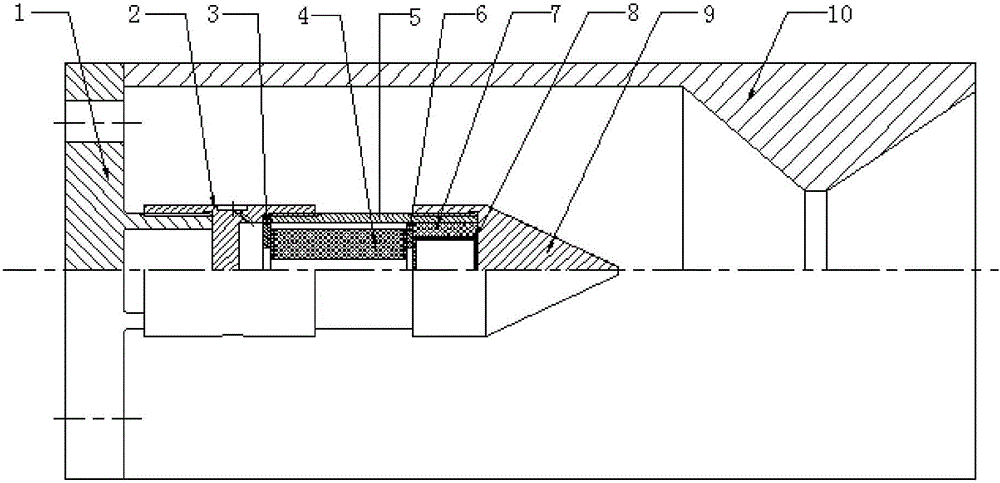
[0021] combine figure 1 :
[0022] An ignition device for a paste propellant gas generator based on a solid rocket motor, comprising an orifice plate seat 1, a gas generator combustion chamber 10 and an ignition engine, wherein the ignition engine includes an ignition engine rear seat 2, a drug retaining plate 3, a point Gunpowder column 4, ignition engine combustion chamber 5, solid medicine plate 6, solid medicine plate positioning seat 7, ignition medicine box 8 and ignition engine front cone 9; 2 and the front cone 9 of the ignition engine are fixedly connected by threads, and the ignition powder column 4 is placed in the combustion chamber 5 of the ignition engine. The medicine-fixing plate 6, the medicine-fixing plate 6 and the front cone 9 of the ignition engine are provided with a medicine-fixing plate positioning seat 7 and an ignition medicine box 8, and the cavity wall between the medicine retaining plate 3 and the rear seat 2 of the ignition engine is evenly Four...
PUM
 Abstract
Description
Claims
Application Information
 - Generate Ideas
- Intellectual Property
- Life Sciences
- Materials
- Tech Scout
- Unparalleled Data Quality
- Higher Quality Content
- 60% Fewer Hallucinations
Browse by: Latest US Patents, China's latest patents, Technical Efficacy Thesaurus, Application Domain, Technology Topic, Popular Technical Reports.
© 2025 PatSnap. All rights reserved.Legal|Privacy policy|Modern Slavery Act Transparency Statement|Sitemap|About US| Contact US: help@patsnap.com