Electronically controlled inlet metered single piston fuel pump

A fuel pump and inlet technology, which is applied in the control field of high-pressure fuel supply pumps, can solve the problems of high audible noise, high pressure pulse, etc., and achieve the effect of reducing the noise level

Active Publication Date: 2015-10-28
STANDYNE INC
View PDF8 Cites 9 Cited by
  • Summary
  • Abstract
  • Description
  • Claims
  • Application Information

AI Technical Summary

Problems solved by technology

These embodiments suffer from high audible noise associated with high speed on/off solenoid operated valve switching shocks
Additionally

Method used


Image

  • Electronically controlled inlet metered single piston fuel pump
  • Electronically controlled inlet metered single piston fuel pump
  • Electronically controlled inlet metered single piston fuel pump

Examples


Embodiment Construction

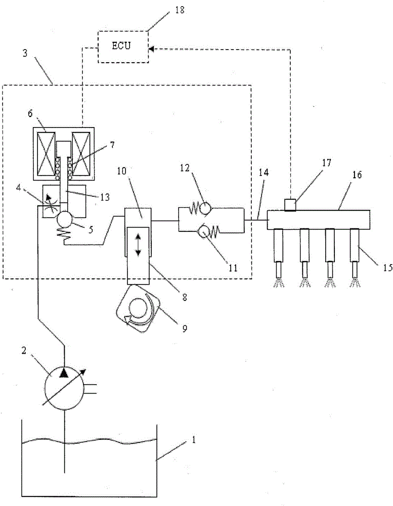
[0017] Referring to the drawings, in which like numerals represent like components, figure 1 Shown is a schematic diagram of an injection system including an electronically controlled inlet metering single-piston fuel pump.

[0018] Pump 2 draws fuel from fuel tank 1 and pumps it through the fuel line on the chassis to the inlet passage of high pressure GDI pump 3. The fuel then flows through the variable opening or orifice 4 of the inlet metering (throttling) valve, then through the inlet check valve 5, and enters during the suction stroke of the boost or during the suction stroke of the pumping plunger 8. pumping chamber 10. An inlet check valve 5 is provided between the metering valve 13 and the pumping chamber 10, said inlet check valve being biased to allow flow to be supplied to the pumping chamber at said inlet section and to prevent high pressure fuel during the pumping phase into the feed channel.

[0019] During the pumping stroke, the pumping plunger 8 is driven ...


PUM


Abstract

A single piston fuel pump comprising a pump housing a pump inlet and an outlet. The pump housing mounts a proportional solenoid operated inlet metering valve with variable orifice, an inlet check valve, a pumping chamber, a pumping piston, an outlet check valve, and a pressure relief valve, wherein the inlet metering valve, the inlet check valve, the outlet check valve, and the pressure relief valve are all mounted on a common axis.

Description

technical field [0001] The invention relates to the control of a high pressure fuel supply pump. Background technique [0002] For initial auto equipment manufacturers, the cost of gasoline direct injection (GDI) fuel systems will be higher than traditional multi-point injection (MPI) systems. In addition to the low-pressure feed pump in the fuel tank, the GDI system requires an engine with a high-pressure pump installed. It has been proven that the higher the pressure required for a GDI system, the higher its noise level. Over the past few years, some gains have been made in reducing the cost of GDI fuel pumps through structural simplification and downsizing. However, noise remains a major complaint from customers. [0003] Current GDI pumps disclosed in U.S. Patent No. 7,401,594 by Hitachi and U.S. Patent No. 7,707,996 by Bosch employ digital on / off electronic valve controllers for accurate alignment of the inlet check valve relative to the cam The opening and closing ...

Claims


Application Information

Patent Timeline
IPC IPC(8): F02M59/20
CPCF02M37/0058F04B1/0452F04B7/0076F04B53/1082F02M59/367F02M59/368F02M2200/09F02M59/366
Inventor R·G·卢卡斯
Owner STANDYNE INC
Why Eureka
Try Eureka