Integrated surgical instrument drive device with decoupling function

A technology of surgical instruments and driving devices, which is applied in the direction of surgery, surgical instruments, obstetrics and gynecology instruments, etc. It can solve the problems of unfavorable adjustment of the position of surgical instruments and easy vibration of the system, so as to reduce the working area, increase the volume and quality, reduce the The effect of collision probability

Active Publication Date: 2015-11-04
杭州唯精医疗机器人有限公司
View PDF10 Cites 10 Cited by
  • Summary
  • Abstract
  • Description
  • Claims
  • Application Information

AI Technical Summary

Problems solved by technology

[0004] The purpose of the present invention is to solve the problem that the drive motor arrangement of the existing surgical instruments increases the drive torque of the joints, making the system prone to vibrations. At the same time, the translational movement of surgical instruments is often driven by nuts and leadscrews, which is not conducive to surgery. Before adjusting the position of surgical instruments

Method used


Image

  • Integrated surgical instrument drive device with decoupling function
  • Integrated surgical instrument drive device with decoupling function
  • Integrated surgical instrument drive device with decoupling function

Examples


specific Embodiment approach 1

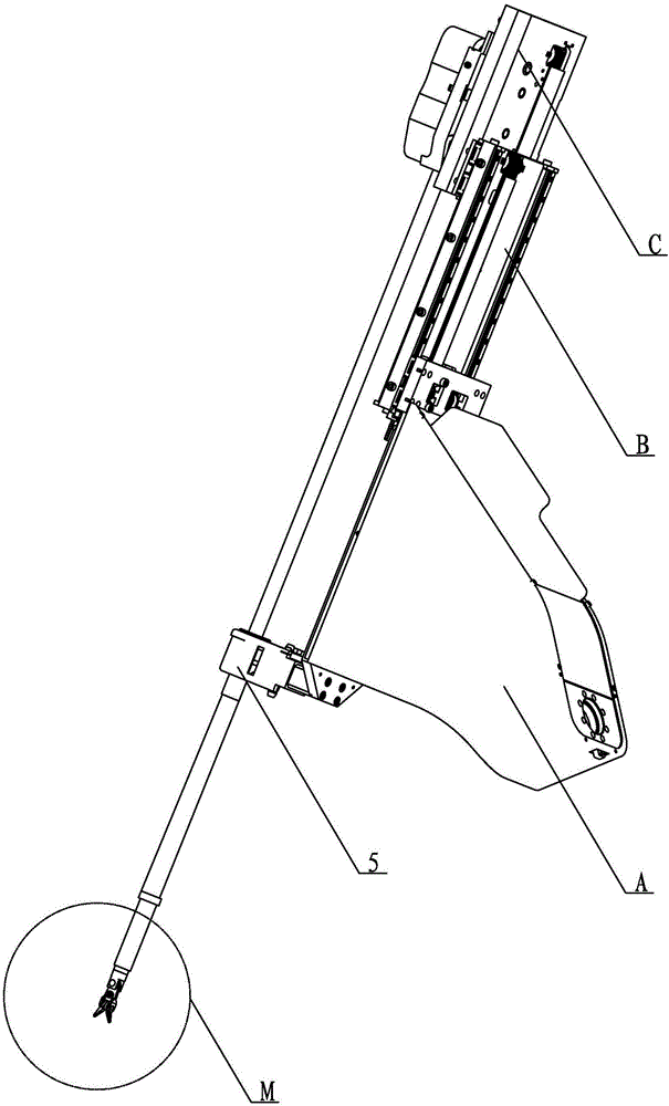
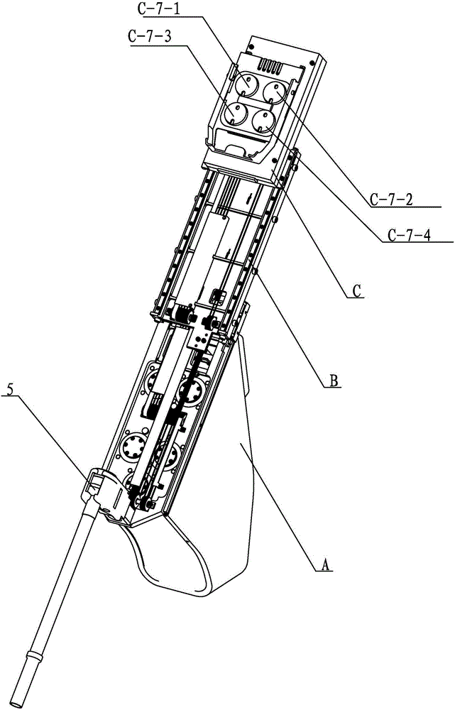
[0019] Specific implementation mode one: combine Figure 1-Figure 35 Describe this embodiment. This embodiment includes a power source assembly A, a decoupling transition assembly B, an interface assembly C, and multiple winding wires D. The power source assembly A, decoupling transition assembly B, and interface assembly C can slide sequentially from bottom to top are interlaced and connected in a decoupled winding manner by a plurality of winding wires D,

[0020] The power source assembly A includes a drive support plate A-1, a drive assembly A-2, a guide wheel assembly A-3 and a slider assembly A-4, and the drive assembly A-2 is installed on the first drive support of the drive support plate A-1 On the end surface A-1-a of the plate, the guide wheel assembly A-3 is installed on the second drive support plate end surface A-1-b, the third drive support plate end surface A-1-c and the second drive support plate end surface A-1-c of the drive support plate A-1 respectively. O...

specific Embodiment approach 2

[0023] Specific implementation mode two: combination Figure 19 Explain that the power source assembly A of this embodiment also includes a power source cover A-5, a driver A-8, a guide shaft A-6 and a winding wire fixing assembly A-7 at the power source, and the power source cover A-5 Covered on the drive support frame A-1 and multiple drive components A-2, the winding wire fixing component A-7 at the power source is installed on the drive support plate A-1, the driver A-8 and the guide shaft A-6 are installed On drive support frame A-1. With this embodiment set up in this way, the power supply is more stable. The undisclosed technical features in this embodiment are the same as those in the first embodiment.

specific Embodiment approach 3

[0024] Specific implementation mode three: combination Figure 23 and Figure 33 Explain that the drive assembly A-2 of this embodiment includes five motor drive assemblies, respectively the first motor drive assembly A-2-a, the second motor drive assembly A-2-b, the third motor drive assembly A-2- c. The fourth motor drive assembly A-2-d and the fifth motor drive assembly A-2-e, wherein the structures of the five motor drive assemblies are the same and different in that the helix of the second motor drive assembly A-2-b The wheel is a double wire wheel A-2-9, and the first motor drive assembly A-2-a includes a drive motor A-2-1, a motor support frame A-2-2, a harmonic reducer A-2-3, Drive spiral wheel A-2-4, drive rotation shaft A-2-5, drive spiral support block A-2-6 and drive cover A-2-7, drive motor A-2-1 is installed on the motor support frame One end of the body A-2-2, one end of the driving screw shaft A-2-5 is connected with the flex spline of the harmonic reducer A-...


PUM


Abstract

The invention relates to an integrated surgical instrument drive device, in particular to an integrated surgical instrument drive device with a decoupling function so as to solve the problems that due to the arrangement mode of a drive motor of an existing surgical instrument, drive torque of joints is increased, a system shakes easily, and meanwhile translational motion of the surgical instrument is generally driven in a nut lead screw mode, which is unbeneficial for adjusting the position of the surgical instrument before an operation. The drive device comprises a power source assembly (A), a decoupling transition assembly (B), a connector assembly (C) and a plurality of winding wires (D). The power source assembly (A), the decoupling transition assembly (B) and the connector assembly (C) are sequentially staggered and stacked in a sliding mode from bottom to top, and connected through the winding wires (D) in a decoupling winding mode. The drive device is used for driving a surgical instrument of a robot surgical micro-instrument.

Description

technical field [0001] The invention relates to an integrated surgical instrument drive device, in particular to an integrated surgical instrument drive device with a decoupling function. Background technique [0002] At present, minimally invasive surgery is a hot spot in medical technology research, and it is the development trend of future surgery, mainly because minimally invasive medicine has many advantages: such as less trauma, shorter hospital stay, faster recovery, and fewer postoperative complications. However, traditional endoscopic surgery has many disadvantages, such as low operation accuracy, small field of view, small degree of freedom of operation, and doctors are prone to fatigue and trembling; with the development of science and technology, robotic medical assistance technology can well solve these problems. Robot-assisted technology can provide a 3D field of view, which is convenient for doctors to operate. Micro medical devices greatly increase the flexib...

Claims


Application Information

Patent Timeline
Patent Type & Authority Applications(China)
IPC IPC(8): A61B19/00A61B17/94
Inventor 付宜利潘博牛国君张福海封海波王树国
Owner 杭州唯精医疗机器人有限公司
Why Eureka
Try Eureka