External-adjustable constant-pressure pre-tightening device for motorized spindle
An electric spindle and setting technology, which is applied in the direction of large fixed members, metal processing machinery parts, metal processing equipment, etc., can solve problems such as inability to adjust
- Summary
- Abstract
- Description
- Claims
- Application Information
AI Technical Summary
Problems solved by technology
Method used
Image
Examples
Embodiment 1
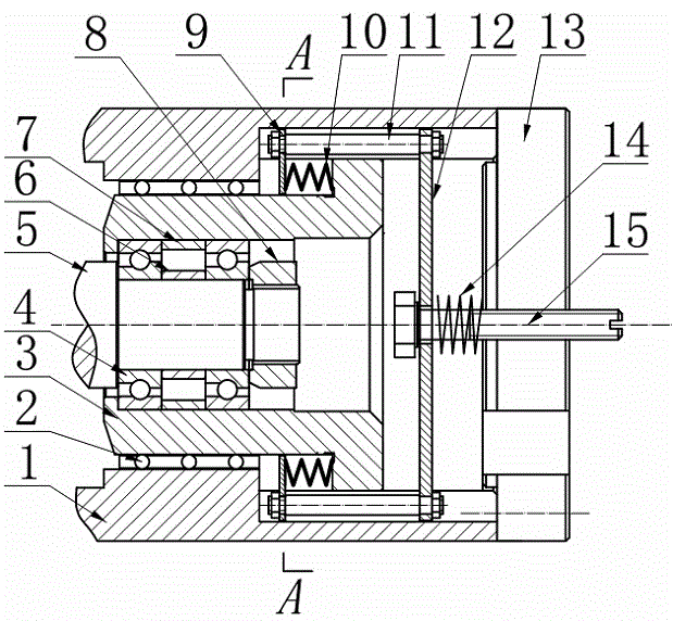
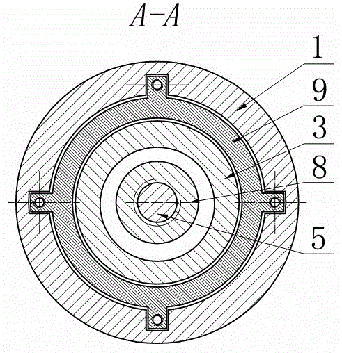
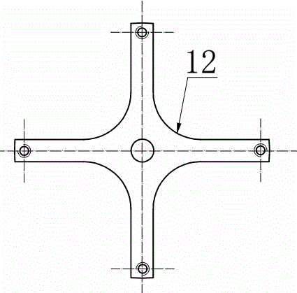
[0025] see Figure 1~Figure 3 , The external adjustable constant pressure preloading device of the electric spindle includes a casing, a rotating shaft 5, a bearing support system and an external adjustable constant pressure preloading system; it is characterized in that: the bearing support system includes a bearing 4, a tightening The fixed nut 8, the inner spacer 6, the outer spacer 7, the bearing seat 3 and the linear bearing 2, the bearing 4 is a pair of angular contact ball bearings arranged in the same direction facing the middle of the rotating shaft, and the two bearings are separated by the inner spacer 6 outside. The spacer 7 is connected and fixed by the shaft shoulder and the fastening nut 8; the bearing 4 is placed in the bearing seat 3, and the bearing seat 3 is placed in the shaft shell 1 through the linear bearing 2; there is an external adjustable constant pressure preload system including Spring 10, spring baffle 9, bolt 11, connecting plate 12, spring 14 an...
Embodiment 2
[0027] see Figure 1~Figure 3 , The external adjustable constant pressure preloading device of this electric spindle is composed of shell, bearing support system, preload adjustment system and other components; the bearing support system consists of bearing 4, inner spacer 6, outer spacer 7, bearing seat 3, The linear bearing 2, the fastening bolt 8, etc. are composed; the pre-tightening adjustment system is composed of the spring baffle 9, the bolt 11, the connecting plate 12, and the adjusting bolt 15. During installation, the bearing seat 3 forms a shoulder at the rear end by the wave spring 10 on the bearing seat 3, the ears of the spring baffle 9 are placed in the groove of the shell 1, and the spring baffle 9 presses the bearing through the wave spring 10 Seat 3, the ears of the spring baffle are connected with bolts 11. The bearing seat 3 is placed in the housing 1 through the linear bearing 2 , the bearing 4 is connected in the bearing seat 3 through the inner spacer ...
PUM
 Abstract
Description
Claims
Application Information
 - R&D
- Intellectual Property
- Life Sciences
- Materials
- Tech Scout
- Unparalleled Data Quality
- Higher Quality Content
- 60% Fewer Hallucinations
Browse by: Latest US Patents, China's latest patents, Technical Efficacy Thesaurus, Application Domain, Technology Topic, Popular Technical Reports.
© 2025 PatSnap. All rights reserved.Legal|Privacy policy|Modern Slavery Act Transparency Statement|Sitemap|About US| Contact US: help@patsnap.com


