Viscous damping wall

A viscous damping wall and viscous damping technology, applied in the field of viscous damping walls, can solve the problems that the shock absorption effect of the viscous damping wall cannot achieve the expected design effect, affect the energy consumption performance of the damping wall, and endanger the safety of buildings, etc. Achieve the effect of increasing the effective contact area, facilitating fabrication and connection, and ensuring out-of-plane stability

Inactive Publication Date: 2015-11-04
SHANGHAI UNIV
View PDF5 Cites 20 Cited by
  • Summary
  • Abstract
  • Description
  • Claims
  • Application Information

AI Technical Summary

Problems solved by technology

[0004] However, this traditional viscous damping wall also has some problems in engineering applications: when the inner steel plate of the traditional viscous damping wall structure performs shearing motion in the viscous material, it is similar to a reciprocating piston.
For general building structures, when a strong earthquake occurs, the inner steel plate of the traditional viscous damping wall may und

Method used


Image

  • Viscous damping wall
  • Viscous damping wall
  • Viscous damping wall

Examples


Embodiment 1

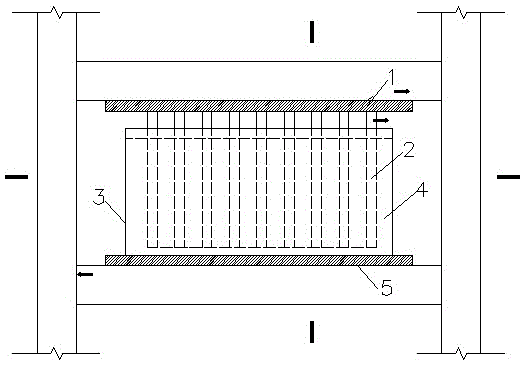
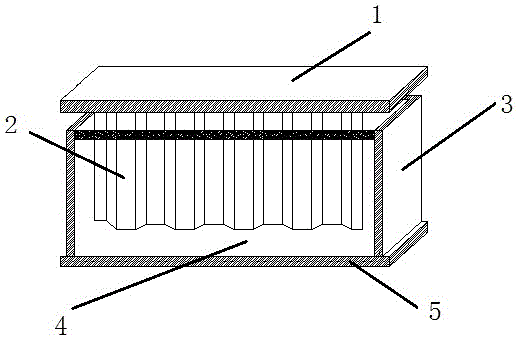
[0019] like figure 1 and figure 2 As shown, a viscous damping wall includes an upper connecting plate 1, an inner steel plate 2, an outer steel box 3, a viscous damping material 4 and a lower connecting plate 5; the inner steel plate 2 is fixed on the middle of the bottom surface of the upper connecting plate 1 , the outer steel box 3 is fixed on the lower connecting plate 5, the outer steel box 3 is filled with a viscous damping material 4, and the inner steel plate 2 is placed in the viscous damping material 4.

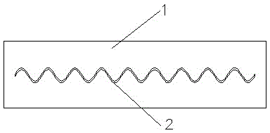
[0020] like Image 6 As shown, the inner steel plate 2 of the present embodiment adopts the curved corrugated mild steel, the height b is 400 mm, the width d is 800 mm, the thickness t is 5 mm, the half-wave amplitude H is 30 mm, and the wavelength is 200mm, the test piece with this parameter has good energy dissipation performance, and no damping hole is opened on the inner steel plate 2.

Embodiment 2

[0022] like image 3 and Figure 5 As shown, this embodiment is basically the same as Embodiment 1, the difference is that the inner steel plate 2 of this embodiment is made of curved mild steel, and the inner steel plate 2 is provided with a damping hole 6, and the shape of the damping hole 6 is circular , the size and position of the damping hole 6 can be adjusted according to the engineering situation.

Embodiment 3

[0024] like Figure 4 and Figure 5 As shown, this embodiment is basically the same as Embodiment 1, the difference is that the inner steel plate 2 of this embodiment adopts trapezoidal corrugated mild steel, and the damping hole 6 is provided on the inner steel plate 2, and the shape of the damping hole 6 is circular. The size and position of the damping hole 6 can be adjusted according to the engineering situation.


PUM

PropertyMeasurementUnit
Widthaaaaaaaaaa
Thicknessaaaaaaaaaa

Abstract

The invention relates to a viscous damping wall. The viscous damping wall comprises an upper connecting plate, inner steel plates, an outer steel box, a viscous damping material and a lower connecting plate, wherein the upper connecting plate is fixed to the bottom of an upper-layer floor beam; the inner steel plates are fixed to the central portion of the bottom surface of the upper connecting plate; the outer steel box is fixed to the lower connecting plate; the lower connecting plate is fixed to the top of a lower-layer floor beam; the outer steel box is filled with the viscous damping material; and the inner steel plates are arranged in the viscous damping material. The inner steel plates are designed into zigzag type soft steel plates, the parameter scopes of an ideal energy consumption test piece are respectively: a height b ranges from 380mm to 420mm, a width d ranges from 780mm to 820mm, a thickness t ranges from 4mm to 6mm, a half-wave amplitude H ranges from 25mm to 35mm, a wavelength lambda ranges from 190mm to 210mm, and a zigzag mode is a curved form or a trapezoidal form. According to the invention, conventional inner steel plates are designed into the zigzag type soft steel plates, and the soft steel plates, compared to conventional inner steel plates, are higher in plasticity, good in processing formability and weldability and is conveniently manufactured and connected.

Description

technical field [0001] The invention relates to a viscous damping wall, which belongs to the technical field of novel energy consumption and shock absorption of building structures. Background technique [0002] Energy dissipation and shock absorption technology is a kind of passive control technology. It is to design some non-load-bearing components of the structure as energy dissipation components, or to set energy dissipation components in certain parts of the structure. Under the action of small earthquakes, the structure has sufficient bearing capacity and rigidity, which can meet the requirements of normal use. Under the action of a large earthquake, the energy-dissipating component generates a large damping force, absorbs and dissipates a large amount of seismic energy, reduces the dynamic response of the main structure, and achieves the purpose of reducing structural damage. Energy dissipation and shock absorption technology is widely used in the anti-seismic and wi...

Claims


Application Information

Patent Timeline
IPC IPC(8): E04B2/00E04B1/98
Inventor 郭煜石文龙
Owner SHANGHAI UNIV
Why Eureka
Try Eureka