Motor drives and electrical equipment using them

A driving device and motor technology, applied in the direction of motor control, starting device, AC motor control, etc., can solve problems such as poor starting, and achieve low-cost effects

Active Publication Date: 2018-06-01
PANASONIC INTELLECTUAL PROPERTY MANAGEMENT CO LTD
View PDF5 Cites 0 Cited by
  • Summary
  • Abstract
  • Description
  • Claims
  • Application Information

AI Technical Summary

Problems solved by technology

The second existing motor driving device uses a small-capacity smoothing capacitor
However, when a high duty ratio with a minimum duty ratio width is ensured from the start, there are startup failures due to excessive voltage, overcurrent, and demagnetization of the rotor permanent magnet of the brushless DC motor accompanying the overcurrent. etc.

Method used


Image

  • Motor drives and electrical equipment using them
  • Motor drives and electrical equipment using them
  • Motor drives and electrical equipment using them

Examples


Embodiment approach 1

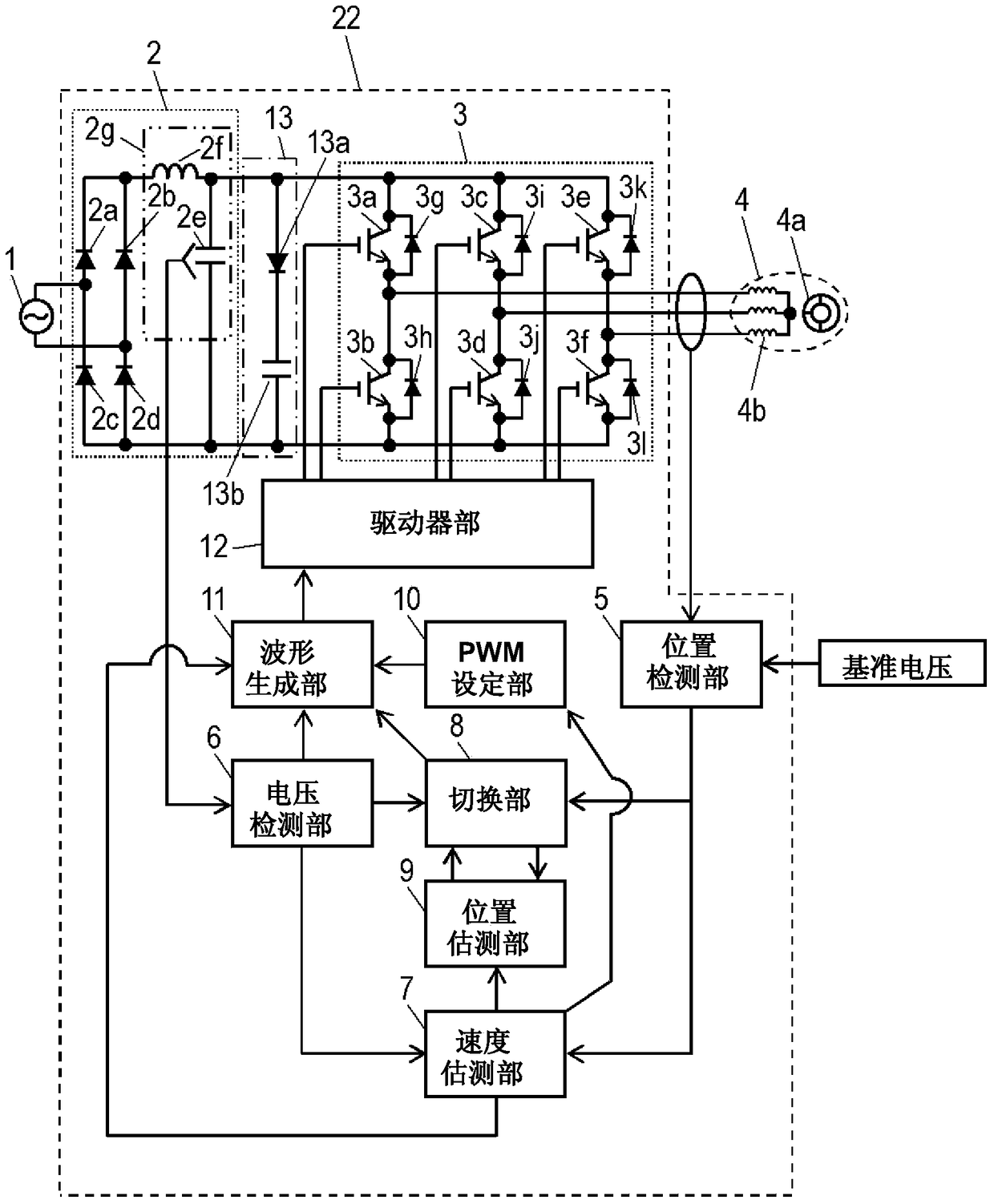
[0061] figure 1 It is a block diagram including the motor drive device 22 according to Embodiment 1 of the present invention.

[0062] exist figure 1 Among them, the AC power supply 1 is a general industrial frequency power supply, which is a 50 or 60 Hz power supply with an effective value of 100V in Japan. The motor drive unit 22 is connected to the AC power source 1 and drives the brushless DC motor 4 . Below, use figure 1 The motor drive device 22 will be described.

[0063] The rectifying and smoothing circuit 2 is a circuit for rectifying and smoothing the AC power generated by the AC power supply 1 into DC power, and includes four bridge-connected rectifying diodes 2a to 2d, a smoothing capacitor 2e, and a reactor 2f. The output of the rectification smoothing circuit 2 is input to the inverter 3 .

[0064] In addition, the smoothing capacitor 2e and the reactor 2f constitute the smoothing unit 2g, and are set so that the resonance frequency becomes a frequency 4...

Embodiment approach 2

[0123] Image 6 It is a block diagram of refrigerator 21 in Embodiment 2 of this invention.

[0124] exist Image 6 in, right with figure 1 The same symbols are attached to the same components, and detailed descriptions thereof are omitted.

[0125] Refrigerator 21 of the present embodiment uses motor drive device 22 of Embodiment 1. As shown in FIG.

[0126] In this embodiment, a reciprocating compressor 17 is used.

[0127] In the compressor 17, the rotational motion of the rotor 4a of the brushless DC motor 4 is converted into a reciprocating motion by a crankshaft (not shown). A piston (not shown) connected to the crankshaft reciprocates in a cylinder (not shown), thereby sucking in refrigerant, compressing it, and circulating it.

[0128] As the compression method (mechanism method) of the compressor, any method such as a rotary type or a scroll type can be used, and a reciprocating type is used in this embodiment. The reciprocating compressor 17 has a large inerti...


PUM


Abstract

A motor drive device (22) includes: a rectifying and smoothing circuit (2) for rectifying the inputted AC current to DC current; and an inverter (3) for converting DC current output from the smoothing circuit (2) to three-phase AC current and driving a brushless DC motor (4). The motor drive device (22) further includes: a position detector (5) for detecting the rotational position of the brushless DC motor (4); and a speed estimation unit (7) for estimating the driving speed of the brushless DC motor (4) from a signal detected by the position detector (5). The motor drive device (22) still further includes: a PWM setting unit (10) for setting the on-duty and carrier frequency using pulse width modulation on the basis of the driving speed such that the carrier frequency is reduced to lower than the carrier frequency having an on-duty greater than a prescribed value by maintaining a constant PMW minimum pulse width when the on-duty is lower than a prescribed value; and a waveform generation unit (11) for generating a driving waveform for the inverter (3) by superimposing the on-duty and the carrier frequency set by the PWM setting unit onto the rotational position and the driving speed.

Description

technical field [0001] The present invention relates to a motor drive device for driving a brushless DC motor and an electric device using the same. Background technique [0002] Figure 7 is a block diagram including a first conventional motor drive device. [0003] A first conventional motor drive device performs square-wave drive with speed feedback control by pulse width modulation (Pulse Width Modulation, hereinafter referred to as PWM) control so that the drive speed matches a target speed. [0004] use Figure 7 A first conventional motor drive device will be described. [0005] The AC power generated by the AC power supply 201 is converted into DC power by the rectifying and smoothing unit 202 . The converted DC power is input to the inverter 203 . The inverter 203 is configured by connecting six switching elements 203a to 203f in a three-phase bridge. Inverter 203 converts the input DC power into AC power of a predetermined frequency, and outputs it to brushless...

Claims


Application Information

Patent Timeline
Patent Type & Authority Patents(China)
IPC IPC(8): H02P6/06H02P6/16H02P6/08H02P6/17H02P6/18H02P6/182H02P6/21
CPCH02P6/182H02P27/085H02P2207/05
Inventor 田中秀尚竹冈义典
Owner PANASONIC INTELLECTUAL PROPERTY MANAGEMENT CO LTD
Why Eureka
Try Eureka