Low-temperature lubricating supply device, high-speed stamping die with same and control method thereof

A supply device and low-temperature lubrication technology, which is applied in the direction of lubricating parts, engine lubrication, forming tools, etc., can solve the problems of shortening the service life of high-speed stamping dies, heat dissipation, and reducing plasticity, so as to ensure stamping accuracy and production efficiency , Reduce deformation and damage, improve service life

Inactive Publication Date: 2015-11-11
苏州明和行新材料科技有限公司
View PDF5 Cites 5 Cited by
  • Summary
  • Abstract
  • Description
  • Claims
  • Application Information

AI Technical Summary

Problems solved by technology

[0002] High-speed stamping die is an indispensable process equipment in modern stamping production. The high-speed precision progressive stamping technology applied to it is a high-efficiency, high-precision advanced manufacturing technology, which represents the development level and development direction of precision stamping technology. The existing The high strain rate of the high-speed stamping die during stamping will lead to the strain strengthening effect of the processed workpiece and reduce the plasticity while dissipating a large amount of heat. In this way, the frictional heat generated will cause a high temperature effect inside the high-speed stamping die, which will lead to The processed workpiece and the high-speed stamping die itself are thermally deformed, which affects the precision of the processed workpiece, making the high-speed stamping die itself easily damaged and scrapped due to high temperature, seriously affecting the service life of the high-speed stamping die
[0003] For this reason, various solutions have been proposed for the high temperature problem in actual high-speed stamping. For example, Chinese patent application publication number 102233385A discloses a high-speed stamping die with a cooling Set the cooling pipeline, the coolant in the cooling pipeline can transfer the heat generated in the stamping process from the inside of the high-speed stamping die in a timely manner by means of heat exchange, reducing the temperature of the high-speed stamping die. However, the above-mentioned high-speed stamping die is used The flowing liquid in the pipeline cools down the mold, which mainly reduces the overall temperature of the mold, and cannot cool parts such as the punching edge, the side wall of the punch, and the insert frame, and the cooling effect is not obvious, while the punching edge The current method is to blow cold air to the mold, but it can only cool down the mold as a whole, and the local temperature is still high
[0004] In addition, in the production of high-speed precision progressive stamping, the frequent contact between the mold and the processed material, the punch and the discharge insert, and the material and the lower die edge causes friction. Due to the small blanking gap, the parts are worn, which not only affects the high-speed Stamping accuracy, and shorten the service life of high-speed stamping dies; in order to avoid the wear between parts and affect the performance of high-speed stamping dies, it is often necessary to oil the parts of high-speed stamping dies at the same time, the existing equipment For example, the Chinese patent application whose publication number is CN102233373 proposes a high-speed stamping die with a lubricating structure; at least one lubricating oil groove is provided inside the die, and the lubricating oil flows into the position to be lubricated, and it is filled with oil. , the lubricating structure in this way will splash around during the stamping process, which will cause serious pollution to the mold and machine tool, inconvenient cleaning, and bring great troubles to the operator. At the same time, it is impossible to actively clean the parts Lubrication under pressure

Method used


Image

  • Low-temperature lubricating supply device, high-speed stamping die with same and control method thereof
  • Low-temperature lubricating supply device, high-speed stamping die with same and control method thereof
  • Low-temperature lubricating supply device, high-speed stamping die with same and control method thereof

Examples


Embodiment Construction

[0038] The present invention will be described in detail below in conjunction with specific embodiments shown in the accompanying drawings. However, these embodiments do not limit the present invention, and any structural, method, or functional changes made by those skilled in the art according to these embodiments are included in the protection scope of the present invention.

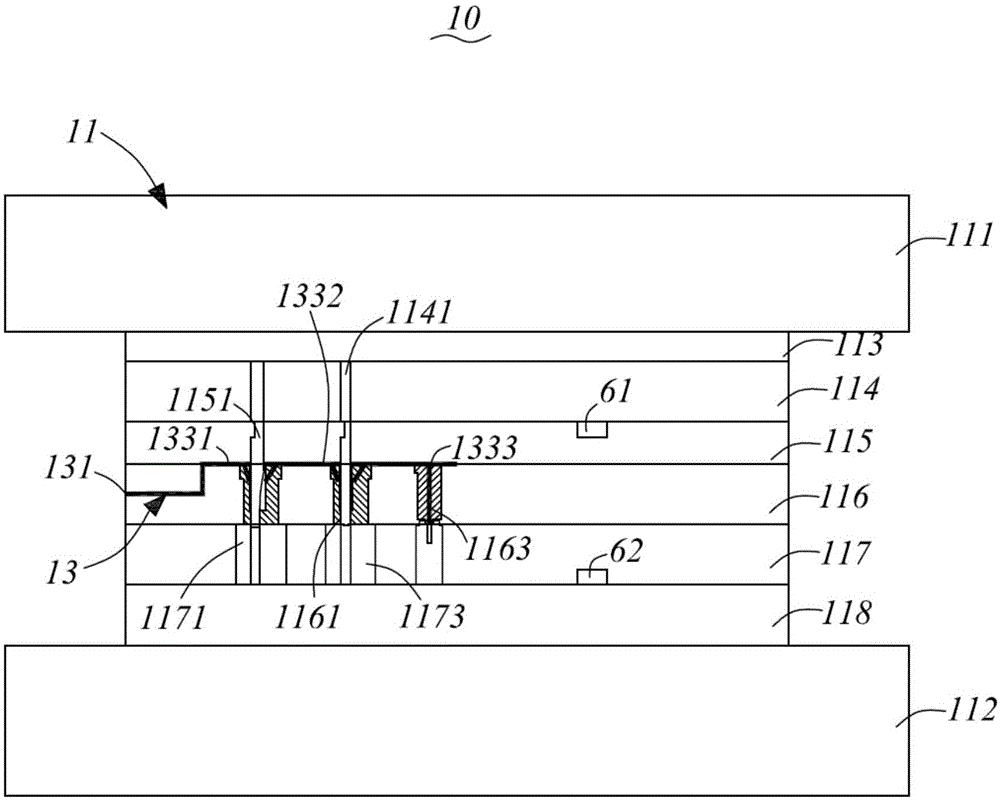
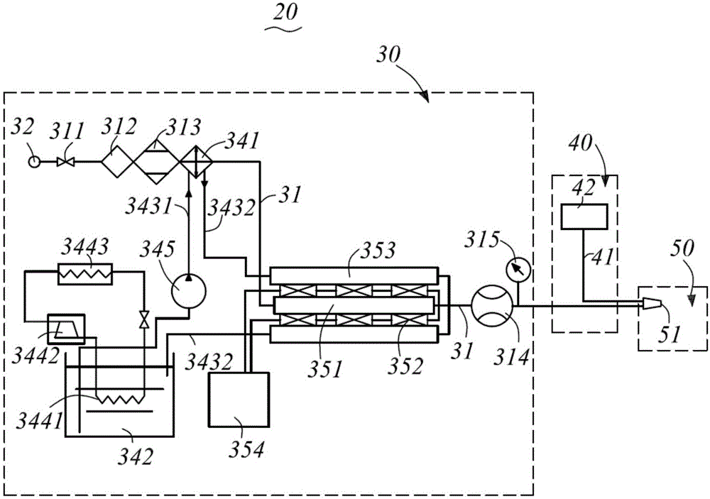
[0039] combine figure 1 , figure 2 As shown, the high-speed stamping die provided by the present invention includes: a stamping body 10 , and a low-temperature lubrication supply device 20 .

[0040] The stamping body 10 includes: a stamping processing area 11 , and oil and gas passages 13 distributed in the stamping body.

[0041] The stamping processing area 11 includes: an upper die base 111, a lower die base 112, and a forming plate group (not shown) arranged between the upper die base 111 and the lower die base 112, and the forming plate set is sequentially arranged from top to bottom Includin...


PUM


Abstract

The invention provides a low-temperature lubricating supply device, a high-speed stamping die with the same and a control method thereof. The low-temperature lubricating supply device comprises a gas supply part for conveying gas, an oil supply part for conveying lubricating oil and an oil-gas mixing part simultaneously communicated with the gas supply part and the oil supply part. The oil-gas mixing part is used for conveying an oil-gas mixed medium formed after the mixing of the gas and the lubricating oil. The gas supply part comprises a gas supply main pipeline. The gas supply part further comprises a vapor compression refrigeration device and a semiconductor refrigeration device which are partially arranged on the gas supply main pipeline and sequentially cool the gas supply main pipeline. According to the low-temperature lubricating supply device, by utilizing forced convection of low-temperature cold gas and phase-change heat exchange of the lubricating oil in the oil-gas mixed medium, heat generated in the working process of a stamping machining area and heat generated during part machining are taken away timely, and the abrasion to the high-speed stamping die is reduced through a lubricating film formed by the lubricating oil.

Description

technical field [0001] The invention belongs to the technical field of molds, and in particular relates to a low-temperature lubrication supply device, a high-speed stamping mold with the same and a control method thereof. Background technique [0002] High-speed stamping die is an indispensable process equipment in modern stamping production. The high-speed precision progressive stamping technology applied to it is a high-efficiency, high-precision advanced manufacturing technology, which represents the development level and development direction of precision stamping technology. The existing The high strain rate of the high-speed stamping die during stamping will lead to the strain strengthening effect of the processed workpiece and reduce the plasticity while dissipating a large amount of heat. In this way, the frictional heat generated will cause a high temperature effect inside the high-speed stamping die, which will lead to The processed workpiece and the high-speed st...

Claims


Application Information

Patent Timeline
Patent Type & Authority Applications(China)
IPC IPC(8): B21D37/18B21D37/16B21D37/10F16N7/30F16N39/02
Inventor 陈明和胡道春张涛王伟锋
Owner 苏州明和行新材料科技有限公司
Why Eureka
Try Eureka