Supercharge Your Innovation With Domain-Expert AI Agents!

Slurry supply system of ceramic sanitary ware high-pressure slurry injection production line

A high-pressure grouting and production line technology, applied in supply devices, manufacturing tools, etc., can solve the problems of not being too long, reducing mud performance, and large fluctuations in slurry temperature, avoiding local overheating, meeting slurry supply requirements, and improving quality. Effect

Inactive Publication Date: 2015-11-11
SHUNDE AREA FOSHAN LEHUA CERAMIC SANITARY WARE
View PDF8 Cites 0 Cited by
  • Summary
  • Abstract
  • Description
  • Claims
  • Application Information

AI Technical Summary

Problems solved by technology

Although the transportation pipeline adopts insulation measures, under the influence of environment, equipment failure and other factors, it is easy to cause large fluctuations in slurry temperature, and the temperature of the slurry cannot meet the process requirements when it reaches the mold
Some slurry supply systems heated by heating wires can also cause partial overheating of the slurry, which reduces the performance of the slurry and affects product quality
Furthermore, the conveying pipe has heat loss and cannot be too long. Therefore, the number of grouting machines that can be connected to the conveying pipe is limited and cannot meet the grout supply requirements of more grouting machines

Method used


Image

  • Slurry supply system of ceramic sanitary ware high-pressure slurry injection production line
  • Slurry supply system of ceramic sanitary ware high-pressure slurry injection production line
  • Slurry supply system of ceramic sanitary ware high-pressure slurry injection production line

Examples


Embodiment 1

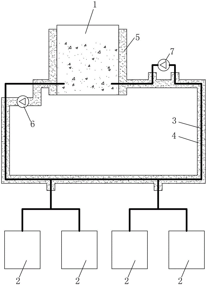
[0012] see figure 1 According to the slurry supply system of a high-pressure grouting production line for ceramic sanitary ware provided by the present invention, it includes a slurry tank 1, a slurry delivery pipe 3 is connected between the slurry tank 1 and the grouting machine 2, and the slurry delivery pipe 3 is wrapped in In the hot water pipe 4. The slurry delivery pipe 3 is represented by a thick solid line among the figures. The interface of the slurry delivery pipe 3 on the mud tank 1 is located below the slurry liquid level in the mud tank 1 . The mud tank 1 is provided with an agitator (the agitator is omitted in the figure). The outer wall of the mud tank 1 is provided with a hot water interlayer 5 for storing hot water, and the first and last ends of the hot water pipe 4 are connected with the hot water interlayer 5 to form a hot water circulation loop. A water pump 6 is connected in series in the hot water circulation circuit, and the water pump 6 drives the h...

Embodiment 2

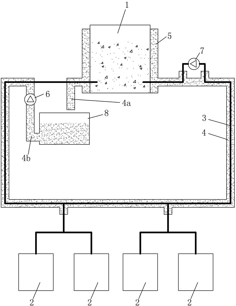
[0017] see figure 2 , the present embodiment adds a reservoir 8 on the basis of the first embodiment. The water storage tank 8 is connected in series in the hot water circulation circuit. The water inlet of the reservoir 8 is connected to the water outlet of the hot water interlayer 5 through a section of hot water pipe 4a, and the water outlet of the reservoir 8 is connected to the suction port of the water pump 6 through another section of hot water pipe 4b. The reservoir 8 has the function of stabilizing the temperature of the hot water, and the reservoir can be used to conveniently adjust the temperature of the hot water, replenish the hot water, adjust the water quality, and achieve the purpose of stably regulating the hot water. The water storage tank 8 can be heated by electricity or by means of a heat exchanger to generate hot water.

[0018] Other structures of this embodiment are the same as those of Embodiment 1.

[0019] In the above example, figure 1 and fi...


PUM


Abstract

A slurry supply system of a ceramic sanitary ware high-pressure slurry injection production line comprises a slurry tank and a slurry delivery pipe connected between the slurry tank and slurry injection machines. A hot water interlayer where hot water can be stored is arranged on the outer wall of the slurry tank; the slurry delivery pipe is wrapped in a hot water pipe, the head end and the tail end of the hot water pipe are connected with the hot water interlayer of the slurry tank, and then a hot water circulation loop is formed; a water pump is connected in the hot water circulation loop in series. According to the slurry supply system, temperature stability in the slurry delivery process is improved, and it is guaranteed that the temperature of slurry arriving at a mould reaches a technically required temperature; besides, slurry in the slurry tank is heated by the hot water, and then local overheating of the slurry can be avoided; all the advantages are beneficial for improving the quality of products formed through slurry injection. In addition, because the slurry is wrapped by the hot water all the time in the delivery process, the slurry delivery pipe can be made very long through connection, more slurry injection machines can be connected to the slurry delivery pipe, and the slurry supply requirement of a large number of slurry injection machines can be met.

Description

technical field [0001] The invention relates to a slurry supply system in a high-pressure grouting production line for ceramic sanitary ware, in particular to the heat preservation technology of the slurry supply system. Background technique [0002] In the high-pressure grouting production line of ceramic sanitary ware, it is necessary to use a slurry supply system to deliver ceramic slurry to multiple grouting machines. During the process of conveying slurry, the slurry supply system must keep the slurry at a certain pressure and temperature. In the existing slurry supply system, the slurry is heated in the slurry tank, and the heated slurry is sent to each grouting machine through the delivery pipe. Although the transportation pipeline adopts insulation measures, under the influence of environment, equipment failure and other factors, it is easy to cause large fluctuations in slurry temperature, and the temperature of the slurry cannot meet the process requirements when ...

Claims


Application Information

Patent Timeline
IPC IPC(8): B28B13/02B28B1/26
CPCB28B13/02B28B1/26
Inventor 谢岳荣刘旭承
Owner SHUNDE AREA FOSHAN LEHUA CERAMIC SANITARY WARE
Features
  • R&D
  • Intellectual Property
  • Life Sciences
  • Materials
  • Tech Scout
  • Unparalleled Data Quality
  • Higher Quality Content
  • 60% Fewer Hallucinations
Learn More