
Mechanical touching type conveyor belt tearing detection method

A detection method and conveyor belt technology, applied in the direction of conveyor objects, conveyor control devices, transportation and packaging, etc., can solve the problems of poor underground transportation conditions, high price, unreliability, etc., and achieve simple, reliable and accurate detection in the detection process The effect of high rate and improved detection efficiency

Active Publication Date: 2015-11-11
LUOYANG TST FLAW DETECTION TECH
View PDF4 Cites 0 Cited by
  • Summary
  • Abstract
  • Description
  • Claims
  • Application Information

AI Technical Summary

Problems solved by technology

However, due to the particularity of the coal mine business, especially the poor underground transportation conditions, the cost of the conveyor belt accounts for as much as 45% of the cost of the whole machine. Once the belt is torn, the conveyor belt worth hundreds of thousands or even millions will be destroyed in a few minutes. It will be severely damaged and bring great direct and indirect economic losses. The research on the detection device for longitudinal tearing of mining conveyor belts is extremely important.
[0003] At present, conveyor belt tear detection equipment is generally developed based on laser ranging or machine vision technology. The detection process of such detection equipment is cumbersome and unreliable, and has radiation hazards to the human body.
In order to solve the above-mentioned problems, the relevant manufacturers have tried their best to find a solution, but for a long time no suitable design has been developed, and the general product has no suitable structure to solve the above-mentioned problems. This is obviously the relevant industry. Urgent problem

Method used


Image

  • Mechanical touching type conveyor belt tearing detection method
  • Mechanical touching type conveyor belt tearing detection method
  • Mechanical touching type conveyor belt tearing detection method

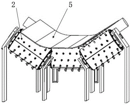
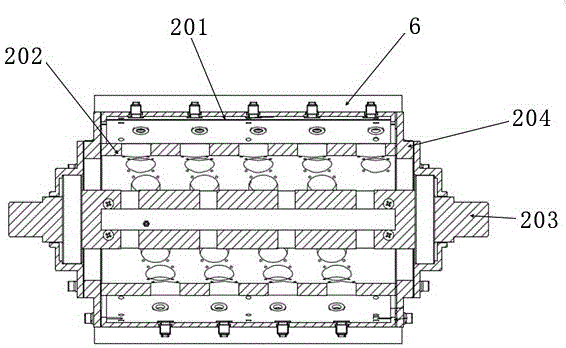
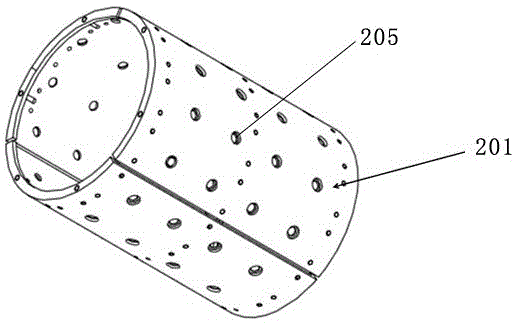
Examples


Embodiment Construction

[0025] Embodiments of the present invention will be described in detail below in conjunction with the accompanying drawings.

[0026] A mechanical touch conveyor belt tear detection method uses a probe 1 arranged on a rotating body 2 that rotates with a conveyor belt 5 to contact the surface of the conveyor belt to form a touch detection. When the conveyor belt 5 is normal, when the probe 1 contacts the conveyor belt with the rotation of the rotating body 2, the conveyor belt 5 presses the probe 1 to compress the elastic element 7, so that the elastic element produces an effect on the probe. needle elasticity. When encountering the torn area on the surface of the conveyor belt, the elastic force applied by the elastic element 7 connected to the probe 1 causes the probe to be inserted into the crack on the surface of the conveyor belt, and when the probe is inserted into the crack, the probe is connected to the probe The trigger mechanism 9 touches the trigger switch 8, and th...


PUM


Abstract

In a mechanical touching type conveyor belt tearing detection method, a probe arranged on a rotating body rotating with a conveyor belt has a contact with the surface of a conveyor belt; when the probe contacts a tearing area of the surface of the conveyor belt, the probe is inserted into the slit in the surface of the conveyor belt via elasticity applied by an elastic element connected with the probe; when the probe is inserted into the slit, a triggering switch is triggered by a triggering mechanism connected with the probe; and a signal is sent to a processing unit by the triggering switch, so a tearing condition of the conveyor belt is determined. A detection process is simple and reliable; harmful effect on on-site equipment can be prevented; an alarm signal is produced when the probe is inserted into the conveyor belt slit; external interference such as light rays, magnetic fields and conveyor belt surface impurities can be avoided; and high detection accuracy is achieved.

Description

technical field [0001] The invention relates to a detection method of a conveyor belt, in particular to a mechanical touch type conveyor belt tear detection method. Background technique [0002] The transportation of coal mines is an important issue in coal mining. As a continuous transportation machine, the belt conveyor is characterized by its continuous operation, large transportation capacity, low power consumption, stable operation, small crushing of materials, and easy automatic control. Widely used in coal transportation. However, due to the particularity of the coal mine business, especially the poor underground transportation conditions, the cost of the conveyor belt accounts for as much as 45% of the cost of the whole machine. Once the belt is torn, the conveyor belt worth hundreds of thousands or even millions will be destroyed in a few minutes. It will be severely damaged and bring great direct and indirect economic losses. The research on the detection device f...

Claims


Application Information

Patent Timeline
IPC IPC(8): B65G43/02
Inventor 杨晓序窦伯英张卫东李志明贴宏波
Owner LUOYANG TST FLAW DETECTION TECH
Learn More