Gradient coil for joint magnetic resonance imaging

A technology of magnetic resonance imaging and gradient coils, applied in the direction of measuring magnetic variables, measuring devices, instruments, etc., can solve the problems of long length, low gradient linearity, and low switching rate

Inactive Publication Date: 2015-11-11
北京斯派克科技发展有限公司
View PDF6 Cites 9 Cited by
  • Summary
  • Abstract
  • Description
  • Claims
  • Application Information

AI Technical Summary

Problems solved by technology

Early (80s of last century) gradient coil products have longer length, low switching rate, low gradient linearity, and relatively weak gradient (less than 20mT / m)

Method used


Image

  • Gradient coil for joint magnetic resonance imaging
  • Gradient coil for joint magnetic resonance imaging
  • Gradient coil for joint magnetic resonance imaging

Examples


Embodiment Construction

[0020] The present invention will be further described below in conjunction with the accompanying drawings and specific embodiments.

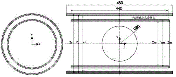
[0021] figure 1 is a schematic diagram of the gradient coil structure used in joint magnetic resonance imaging. The outer layer is a shielding coil layer. An embodiment of the present invention has a length of 480mm, and from the outside to the inside are the Z, Y and X coil shielding layers, and the diameters are Zs, Ys and Xs respectively. The inner layer is the main coil layer. In one embodiment of the present invention, the length is 440mm, and they are respectively Zm, Ym and Xm in descending order of diameter. There are shim slots and water cooling channels between the main coil layer and the shielding coil layer, and the interval is greater than 15mm. The imaging area is a sphere with a radius of 80mm.

[0022] The coil wiring positions in the embodiment are listed below:

[0023] X coil: main layer Xm=206mm; shielding layer Xs=256mm...


PUM


Abstract

The present invention provides a gradient coil for joint magnetic resonance imaging, consisting of a main gradient coil layer and a shielding coil layer, wherein either of the main gradient coil layer and the shielding coil layer comprises gradient coils in three directions, i.e., X, Y and Z directions, either of a main coil and a shielding coil in each direction is formed by cutting of two layers of copper sheets, the copper sheets are stacked vertically to facilitate a current loop and increase a gradient value; a gap is provided between a main coil layer and a gradient coil layer for arranging a shimming slot and a water cooling channel. The gradient coil has the advantages of short length (not more than 480mm), high gradient field strength (capable of reaching 70mT / m) and good gradient linearity (superior to -2%-+2%), can greatly improve contrast ratio of imaging relative to a gradient coil of a whole body imaging system, and is especially suitable for joint imaging.

Description

technical field [0001] The invention belongs to the field of magnetic resonance imaging, in particular to a gradient coil for joint magnetic resonance imaging. Background technique [0002] The Magnetic Resonance Imaging (MRI) system includes a magnet system, a gradient system, a radio frequency system and a computer imaging system, and is an important image detection method in the medical field today. Among them, the function of the gradient system is to provide a linear and rapidly switchable gradient magnetic field in the imaging area, and provide spatial encoding information for the magnetic resonance radio frequency scan. The early gradient coil products (in the 1980s) had longer lengths, lower switching rates, lower gradient linearity, and weaker gradients (less than 20mT / m). After nearly 40 years of development, gradient coils have developed in the direction of short cavity, high gradient field, high switching rate, and high efficiency. [0003] Joint magnetic reson...

Claims


Application Information

Patent Timeline
Patent Type & Authority Applications(China)
IPC IPC(8): G01R33/385
Inventor 林海洋
Owner 北京斯派克科技发展有限公司
Why Eureka
Try Eureka