Current compensation-based unbalance vibration control system for bearingless asynchronous motor

A technology of asynchronous motor and current compensation, applied in motor generator control, electronic commutation motor control, control system, etc., can solve problems such as limited vibration suppression effect, affecting rotor suspension control accuracy, rotor unbalanced vibration, etc.

Inactive Publication Date: 2015-11-11
HENAN UNIV OF SCI & TECH
View PDF3 Cites 22 Cited by
  • Summary
  • Abstract
  • Description
  • Claims
  • Application Information

AI Technical Summary

Problems solved by technology

As a rotary drive motor, due to uneven material, machining accuracy, assembly errors, etc., there will inevitably be a certain degree of rotor mass eccentricity, which will generate an exciting force at the same frequency as the rotational speed during rotation, resulting in unbalanced vibration of the rotor and affecting Rotor suspension control accuracy
[0003] After searching the existing literature and patents, it is found that there are few research results at home and abroad on the rotor unbalance vibration control technology of bearingless motors, and the existing achievements mainly focus on the synchronous bearingless motor based on static field Balanced vibration, the vibration compensation method is mostly "displacement compensation", and there is no independent control of random displacement and unbalanced displacement, the vibration suppression effect is limited; the bearingless asynchronous motor has the characteristics of a robust mechanical structure and is suitable for high-speed operation, while domestic There are very few reports on the vibration control of external bearingless asynchronous motors; the control of the radial displacement of the bearingless rotor depends on the radial magnetic levitation force, and the control of the magnetic levitation force ultimately depends on the "control current" of the levitation winding

Method used


Image

  • Current compensation-based unbalance vibration control system for bearingless asynchronous motor
  • Current compensation-based unbalance vibration control system for bearingless asynchronous motor
  • Current compensation-based unbalance vibration control system for bearingless asynchronous motor

Examples


Embodiment Construction

[0037] In order to make the content of the present invention more obvious and understandable, the present invention will be described in detail below in conjunction with specific embodiments.

[0038] Core idea of ​​the present invention is:

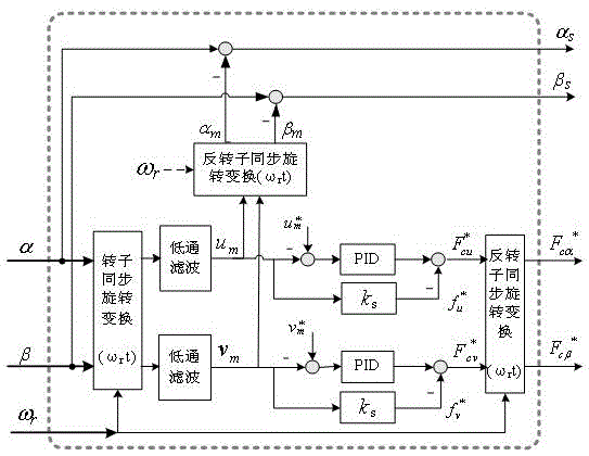
[0039] 1. During the rotation of the bearingless motor rotor, the inevitable rotor mass eccentricity will excite the excitation force in the same direction as the eccentricity; if no vibration control measures are added, under the action of the excitation force, the rotor shaft will The heart produces periodic radial displacement fluctuations or vibrations, that is, unbalanced vibration displacements. The unbalanced vibration displacement signal of the bearingless asynchronous motor rotor is a sinusoidal alternating signal with the same frequency as the rotational speed. Based on this feature, the unbalanced vibration displacement signal can be filtered, tracked and extracted in real time.

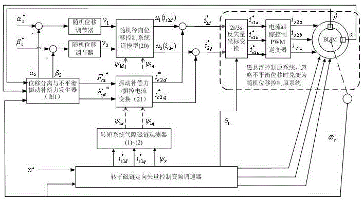
[0040] 2. In order to improve the speed contr...


PUM


Abstract

The invention discloses a current compensation-based unbalance vibration control system for a bearingless asynchronous motor. A rotor flux linkage-oriented vector control variable-frequency governor provides current to a torque winding to control the rotating speed of the motor and the rotor flux linkage; torque winding stator current components and rotor flux linkage signals are output to an air gap flux linkage observer; two linear integration sub-systems are formed before a random displacement control inverse system is connected to the original system in series; rotor radial displacement is fed into a displacement separation and unbalance vibration compensation force generator to obtain random displacement and unbalance vibration compensation force; the random displacement is fed into the inverse system through a random displacement adjustor to form closed loop control; the inverse system outputs random displacement control current; the unbalance vibration compensation force is subjected to force / flow transformation to obtain unbalance vibration compensation control current; the unbalance vibration compensation control current is correspondingly compared with the random displacement control current to obtain synthetic magnetic levitation control current; and the synthetic magnetic levitation control current is fed into the original system to generate three-phase magnetic levitation control current, so that the unbalance vibration current compensation control on the bearingless asynchronous motor is realized.

Description

technical field [0001] The invention relates to the technical field of drive control of special AC motors, and is especially suitable for the high-precision magnetic levitation operation control of a bearingless asynchronous motor, and is a simple and practical rotor unbalance vibration control system for a bearingless asynchronous motor. Background technique [0002] Bearingless motor is based on the similarity between magnetic bearing and AC motor stator structure. It is a new type of motor suitable for high-speed operation developed in recent years. It has broad application prospects in aerospace, material sealing transmission, advanced manufacturing and other fields. As a rotary drive motor, due to uneven material, machining accuracy, assembly errors, etc., there will inevitably be a certain degree of rotor mass eccentricity, which will generate an exciting force at the same frequency as the rotational speed during rotation, resulting in unbalanced vibration of the rotor ...

Claims


Application Information

Patent Timeline
Patent Type & Authority Applications(China)
IPC IPC(8): H02P21/00H02P21/08H02P21/12H02P27/08
Inventor 卜文绍王程远刘磊坡李晓强程相辉乔岩茹肖隽亚路春晓叶宇程
Owner HENAN UNIV OF SCI & TECH
Why Eureka
Try Eureka