Design method of direction modulation signal based on spatial Fourier transform
A technology of Fourier transform and directional modulation, applied in space transmit diversity, modulated carrier system, diversity/multi-antenna system, etc., can solve the problems of reducing algorithm complexity, distortion of relative phase relationship, and inability to demodulate communication information, etc. , to achieve the effect that the design method is simple and intuitive, guarantees the degree of distortion, and is easy to realize in engineering
- Summary
- Abstract
- Description
- Claims
- Application Information
AI Technical Summary
Problems solved by technology
Method used
Image
Examples
Embodiment 1
[0086] Single user channel with pencil phase beam:
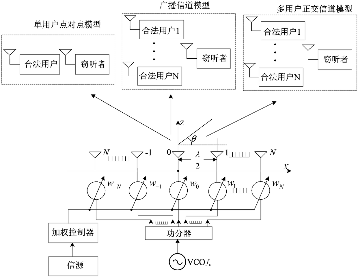
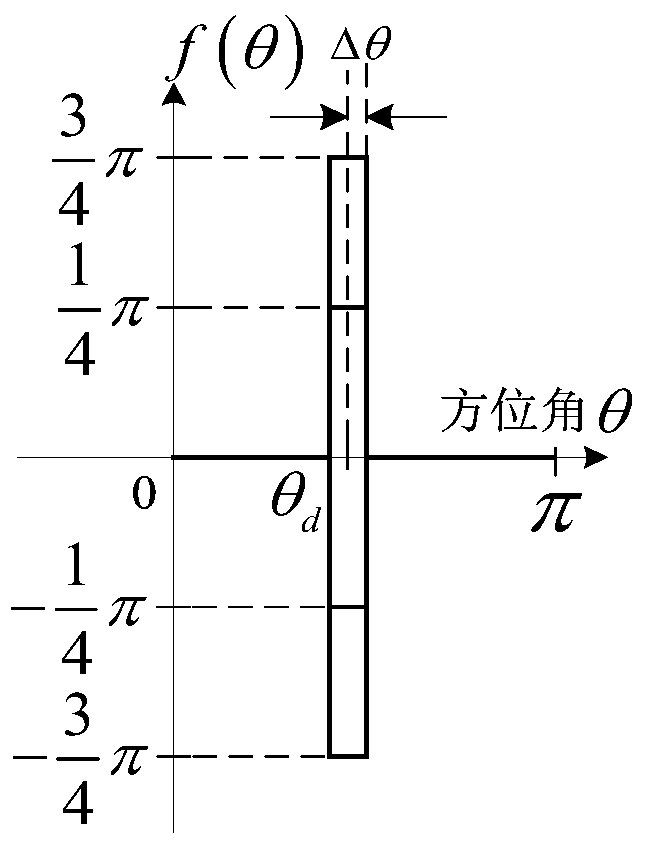
[0087] Let the azimuth θ where the desired receiver is located d =70°, Δθ=6°, the number of elements of the phased array is 13 and the expected digital modulation signal is a QPSK modulation signal. From formulas (5) and (7), we can get the excitation w of the array element k ,k=-N,...,0,...N. Figure 3(a) and 3(b) The comparison diagrams of the relative amplitude and phase of different modulation symbols transmitted by the pencil-shaped phase beam direction modulation signal transmitter and the array element weighted signal of the traditional transmitter are given. Figure 4(a)(c)(c) and Figure 5(a)(b) respectively show the radiation signal pattern function of the pencil-shaped phase beam direction modulation signal transmitter and the traditional transmitter and the constellation diagram of the received signal in different azimuths. It can be seen from the figure that the pencil-shaped phase beam direction modulation si...
Embodiment 2
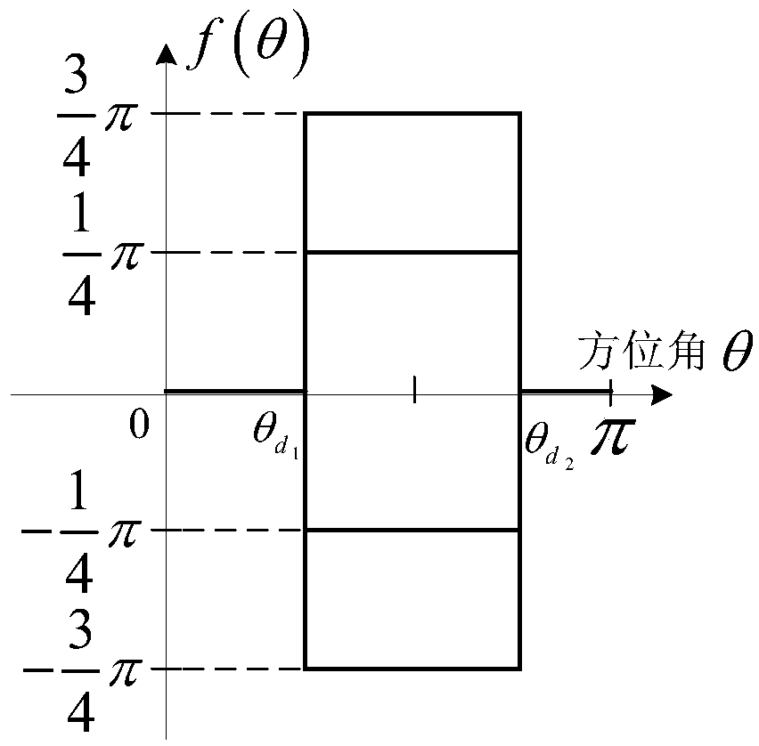
[0090] Broadcast channel for fanned phase beams:
[0091] Let the azimuth range expected to be covered be The number of phased array transmitting elements is 31 and the expected digital modulation signal is QPSK modulation signal. From formulas (5) and (7), we can get the excitation w of the array element k ,k=-N,...,0,...N. Figure 7(a) and 7(b) The comparison diagrams of the relative amplitude and phase of different modulation symbols transmitted by the pencil-shaped phase beam direction modulation signal transmitter and the array element weighted signal of the traditional transmitter are given. Figure 8(a)(b)(c) and Figure 9(a)(b) respectively show the radiation signal pattern function of the fan-shaped phase beam direction modulation signal transmitter and the constellation diagram of the received signal in different azimuths. It can be seen from the figure that the fan-shaped phase beam direction modulation signal transmitter is compared with the traditional transmit...
Embodiment 3
[0094] Multi-user channel with quadrature phase beams:
[0095] Assuming that there are two expected users in the system, the locations are respectively In the algorithm simulation, Δθ=6°, the number of phased array elements is 13 and the expected digital modulation signal is QPSK modulation signal. Since the two users transmit information codes differently, the expected phase function f(θ) has 16 different phase function forms. Next, we use user 1 to send QPSK modulation symbol '11' and user 2 to send QPSK modulation symbol '11' respectively, The phase functions of the four combinations of '1-1', '-11', and '-1-1' are taken as examples to illustrate the design method of the direction modulation signal in this paper. From formulas (5) and (7), we can get the excitation w of the array element k ,k=-N,...,0,...N. Figure 11(a) and (b) show the comparison diagrams of the relative amplitude and phase of different modulation symbols transmitted by the pencil-shaped phase beam di...
PUM
 Abstract
Description
Claims
Application Information
 - R&D
- Intellectual Property
- Life Sciences
- Materials
- Tech Scout
- Unparalleled Data Quality
- Higher Quality Content
- 60% Fewer Hallucinations
Browse by: Latest US Patents, China's latest patents, Technical Efficacy Thesaurus, Application Domain, Technology Topic, Popular Technical Reports.
© 2025 PatSnap. All rights reserved.Legal|Privacy policy|Modern Slavery Act Transparency Statement|Sitemap|About US| Contact US: help@patsnap.com


