
Wrist part two-stage slewing mechanism of small underwater hydraulic manipulator

A technology of hydraulic machinery and slewing mechanism, applied in the direction of manipulators, manufacturing tools, joints, etc., can solve the problems of unsuitable small underwater hydraulic manipulators, affecting the flexibility of manipulators, and bulky volume, etc., to achieve light weight, compact structure, and small volume Effect

Inactive Publication Date: 2015-11-18
HARBIN ENG UNIV
View PDF7 Cites 0 Cited by
  • Summary
  • Abstract
  • Description
  • Claims
  • Application Information

AI Technical Summary

Problems solved by technology

[0003] There are many types of manipulator wrist structures currently disclosed, and most of the current wrist structures suitable for hydraulic manipulators are directly connected by hydraulic motors and hydraulic cylinders. Yes, they are bulky and affect the flexibility of the manipulator. They are not suitable for small underwater hydraulic manipulators.
For example, the Chinese patent application number is 200910071579.X, a hydraulically driven mechanical wrist structure, using a cycloidal motor and a hydraulic cylinder directly connected to use, can realize 360-degree continuous rotation of the wrist, but its structure is relatively large, not suitable for small Used in underwater hydraulic manipulators; for example, the secondary drive joint of a small underwater hydraulic manipulator with Chinese patent application number 2014106411657 has a compact structure, small size and light weight, and can provide flexible wrist rotation for small hydraulic manipulators. Can only rotate 180 degrees

Method used


Image

  • Wrist part two-stage slewing mechanism of small underwater hydraulic manipulator
  • Wrist part two-stage slewing mechanism of small underwater hydraulic manipulator
  • Wrist part two-stage slewing mechanism of small underwater hydraulic manipulator

Examples


Embodiment Construction

[0025] The present invention is described in more detail below in conjunction with accompanying drawing example:

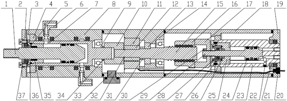
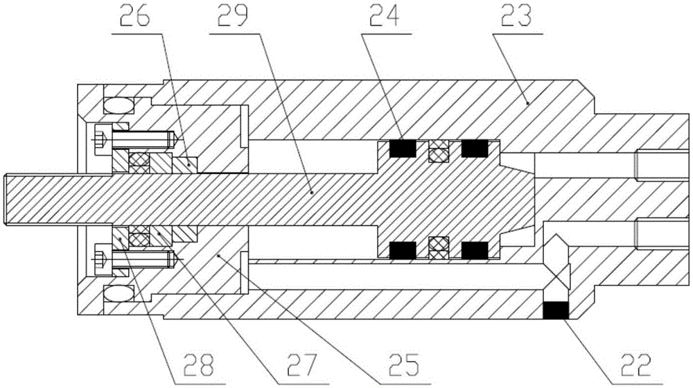
[0026] combine figure 1 ~6, the parts included in the present invention are: output shaft A1, hydraulic cylinder head A2, gray ring 3, sliding bearing A4, copper sleeve A5, connector 6, cylinder barrel A7, front end shell 8, ball bearing A9, coupling Shaft device 10, sensor stator 11, sensor rotor 12, sliding bearing B13, sensor housing 14, output shaft B15, screw nut 16, nut connector 17, rear shell 18, rear end cover 19, signal line 20, sliding bearing C21, welding block 22, drive cylinder 23, rubber guide ring B24, hydraulic cylinder head B25, guide rubber 26, copper sleeve B27, gray ring end cover B28, output shaft C29, nut 30, installation shoulder 31, Circlip 32, plug 33, short shaft shoulder 34, guide ring A35, O-shaped sealing ring 36, gray ring end cap A (37).

[0027] Such as figure 1 As shown, the present invention is mainly composed of a manipulator...


PUM


Abstract

The invention provides a wrist part two-stage slewing mechanism of a small underwater hydraulic manipulator. The wrist part two-stage slewing mechanism of the small underwater hydraulic manipulator mainly comprises a mechanical arm outer shell, a first-stage driving hydraulic cylinder assembly, a linear slewing movement conversion assembly, an angular velocity sensor, a second-stage driving hydraulic cylinder assembly, an outer shell assembly, a sealing assembly and the like. The first-stage driving hydraulic cylinder assembly and the linear slewing movement conversion assembly are connected and installed at the rear end of the mechanism to provide wrist slewing movement. The sensor is installed on a front end movement output shaft of the linear slewing movement conversion assembly, and meanwhile the front end movement output shaft is connected with the tail of the second-stage driving hydraulic cylinder assembly through a coupler. The second-stage driving hydraulic cylinder assembly is installed at the front end of the mechanism to provide linear driving force. A signal cable of the sensor penetrates through the mechanical arm outer shell and is led out from a vulcanized rubber end cover at the tail. The inner space of a mechanical arm can be filled with oil to be sealed, and the depth of the work environment is improved. The wrist part two-stage slewing mechanism of the small underwater hydraulic manipulator can realize continuous slewing within 360 degrees and can detect the slewing angle and angular acceleration.

Description

technical field [0001] The invention relates to an underwater robot, specifically a wrist robot. Background technique [0002] In recent years, robot technology has developed very rapidly, and robots have been widely used in industry, agriculture, service, medical treatment, military and other fields. Manipulator is an important branch of robotics, which can complete various expected tasks. The manipulator can be divided into electric drive, pneumatic drive and hydraulic drive according to its drive mode. The hydraulically driven manipulator has the advantages of smooth movement, large load capacity, good speed, and infinitely variable speed, and is widely used in heavy-duty operations such as underwater operations. The mechanical wrist is the key part of the manipulator, and its flexibility and accuracy determine the flexibility and accuracy of the manipulator to a large extent. Therefore, it is very important to design the mechanical wrist with small volume and good fle...

Claims


Application Information

Patent Timeline
Patent Type & Authority Applications(China)
IPC IPC(8): B25J17/02B25J13/08
Inventor 张铭钧杨超马小委姚峰赵文德
Owner HARBIN ENG UNIV
Features
  • Generate Ideas
  • Intellectual Property
  • Life Sciences
  • Materials
  • Tech Scout
  • Unparalleled Data Quality
  • Higher Quality Content
  • 60% Fewer Hallucinations
Learn More